Lexus ES: Reverse Signal Circuit
DESCRIPTION
The multi-display receives a reverse signal from the BK UP LP relay*1 or clearance warning ECU assembly*2.
- *1: w/o Parking Support Alert System
- *2: w/ Parking Support Alert System
WIRING DIAGRAM
for 8 inch display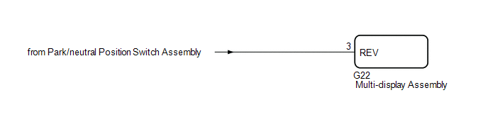 for 12.3 inch display w/ Parking Support Alert System
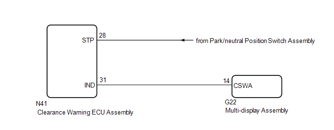
CAUTION / NOTICE / HINT
NOTICE:
-
When "!" mark is displayed on the multi-display assembly after disconnecting the cable from the negative (-) battery terminal, correct the steering angle neutral point.
Click here
.gif)
-
Depending on the parts that are replaced or operations that are performed during vehicle inspection or maintenance, calibration of other systems as well as the parking assist monitor system may be needed.
Click here
PROCEDURE
| 1. | CHECK BACK-UP LIGHT |
(a) Check that the back-up light comes on.
OK:
The back-up light comes on.
| Result | Proceed to |
|---|---|
| OK (for 8 inch display) | A |
| OK (for 12.3 inch display w/ Parking Support Alert System) | B |
| NG | C |
| B | .gif) | GO TO STEP 3 |
| C | | GO TO LIGHTING SYSTEM (EXT) |
|
.gif)
| 2. | CHECK HARNESS AND CONNECTOR (REVERSE SIGNAL) |
(a) Disconnect the G22 multi-display assembly connector.
(b) Measure the voltage according to the value(s) in the table below.
Standard Voltage:
| Tester Connection | Condition | Specified Condition |
|---|---|---|
| G22-3 (REV) - Body ground | Engine switch on (IG) Shift lever in R | 11 to 14 V |
| G22-3 (REV) - Body ground | Engine switch on (IG) Shift lever not in R | Below 1 V |
| OK | | PROCEED TO NEXT SUSPECTED AREA SHOWN IN PROBLEM SYMPTOMS TABLE |
| NG | | REPAIR OR REPLACE HARNESS OR CONNECTOR |
| 3. | CHECK HARNESS AND CONNECTOR (REVERSE SIGNAL) |
(a) Disconnect the N41 clearance warning ECU assembly connector.
(b) Measure the voltage according to the value(s) in the table below.
Standard Voltage:
| Tester Connection | Condition | Specified Condition |
|---|---|---|
| N41-28 (STP) - Body ground | Engine switch on (IG) Shift lever in R | 8V or higher |
| N41-28 (STP) - Body ground | Engine switch on (IG) Shift lever not in R | Below 3 V |
| NG | | REPAIR OR REPLACE HARNESS OR CONNECTOR |
|
| 4. | CHECK HARNESS AND CONNECTOR (CLEARANCE WARNING ECU ASSEMBLY - MULTI-DISPLAY ASSEMBLY) |
(a) Disconnect the N41 clearance warning ECU assembly connector.
(b) Disconnect the G22 multi-display assembly connector.
(c) Measure the resistance according to the value(s) in the table below.
Standard Resistance:
| Tester Connection | Condition | Specified Condition |
|---|---|---|
| N41-31 (IND) - G22-14 (CSWA) | Always | Below 1 Ω |
| N41-31 (IND) or G22-14 (CSWA) - Body ground | Always | 10 kΩ or higher |
| NG | | REPAIR OR REPLACE HARNESS OR CONNECTOR |
|
| 5. | INSPECT CLEARANCE WARNING ECU ASSEMBLY |
| (a) Connect the N41 clearance warning ECU assembly connector. |
|
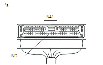
(b) Measure the voltage according to the value(s) in the table below.
Standard Voltage:
| Tester Connection | Condition | Specified Condition |
|---|---|---|
| N41-31 (IND) - Body ground | Engine switch on (IG) Shift lever in R | Below 3 V |
| N41-31 (IND) - Body ground | Engine switch on (IG) Shift lever not in R | 8 V or higher |
| OK | | PROCEED TO NEXT SUSPECTED AREA SHOWN IN PROBLEM SYMPTOMS TABLE |
| NG | | REPLACE CLEARANCE WARNING ECU ASSEMBLY |
READ NEXT:
 System Description
SYSTEM DESCRIPTION GENERAL (a) This system has a rear television camera assembly mounted on the luggage compartment door to display an image of the area behind the vehicle on the multi-display. The mu
System Diagram
SYSTEM DIAGRAM Communication Table Sender Receiver Signal Line Radio Receiver Assembly Multi-display Assembly Camera information signal GVIF Radio Receiver Assembly Rear Tel
Terminals Of Ecu
TERMINALS OF ECU REAR TELEVISION CAMERA ASSEMBLY (a) Disconnect the T1 rear television camera assembly connector. (b) Measure the voltage on the wire harness side connector according to the value(s)
SEE MORE:
Removal
REMOVAL CAUTION / NOTICE / HINT The necessary procedures (adjustment, calibration, initialization, or registration) that must be performed after parts are removed and installed, or replaced during black out tape removal/installation are shown below. Necessary Procedure After Parts Removed/Installed/
Steering Angle Sensor Failure (C1626)
DESCRIPTION
This DTC is stored if the parking assist ECU receives a signal via CAN communication from the steering sensor that indicates an internal malfunction.
This DTC is stored if the rear television camera assembly receives a signal via CAN communication from the steering sensor that indic
