Lexus ES: P/W Master Switch Communication Stop (B1206,B1273,B2321-B2324)
DESCRIPTION
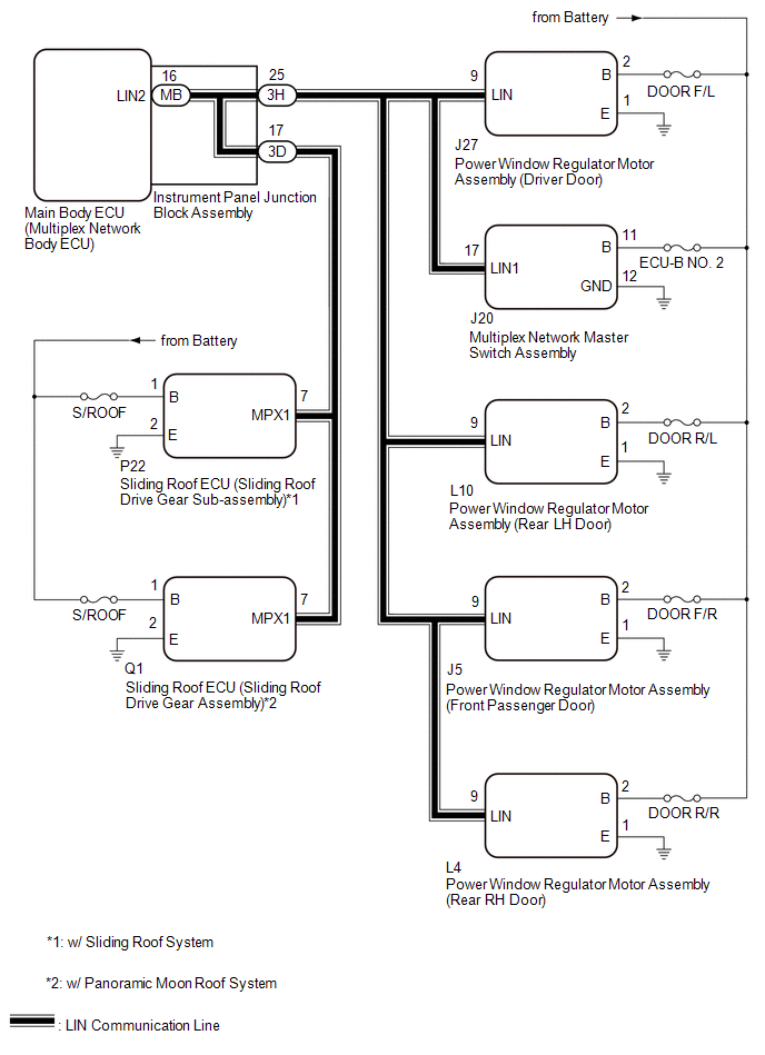
This DTC is stored when LIN communication between the main body ECU (multiplex network body ECU) and multiplex network master switch assembly, sliding roof ECU (sliding roof drive gear sub-assembly)*1, sliding roof ECU (sliding roof drive gear assembly)*2, power window regulator motor assembly (driver door), power window regulator motor assembly (front passenger door), power window regulator motor assembly (rear RH door) or power window regulator motor assembly (rear LH door) stops for 10 seconds or more.
- *1: w/ Sliding Roof System
- *2: w/ Panoramic Moon Roof System
| DTC No. | Detection Item | DTC Detection Condition | Trouble Area |
|---|---|---|---|
| B1206 | P/W Master Switch Communication Stop | No communication between multiplex network master switch assembly and main body ECU (multiplex network body ECU) for 10 seconds or more. |
|
| B1273 | Sliding Roof ECU Communication Stop | No communication between sliding roof ECU (sliding roof drive gear sub-assembly)*2 or sliding roof ECU (sliding roof drive gear assembly)*3 and main body ECU (multiplex network body ECU) for 10 seconds or more. |
|
| B2321 | D-Door Motor ECU Communication Stop | No communication between power window regulator motor assembly (driver door) and main body ECU (multiplex network body ECU) for 10 seconds or more. |
|
| B2322 | P-Door Motor ECU Communication Stop | No communication between power window regulator motor assembly (front passenger door) and main body ECU (multiplex network body ECU) for 10 seconds or more. |
|
| B2323 | RR-Door Motor ECU Communication Stop | No communication between power window regulator motor assembly (rear RH door) and main body ECU (multiplex network body ECU) for 10 seconds or more. |
|
| B2324 | RL-Door Motor ECU Communication Stop | No communication between power window regulator motor assembly (rear LH door) and main body ECU (multiplex network body ECU) for 10 seconds or more. |
|
- *1: w/ Sliding Roof System
- *2: w/ Panoramic Moon Roof System
WIRING DIAGRAM
CAUTION / NOTICE / HINT
NOTICE:
- Inspect the fuses for circuits related to this system before performing the following procedure.
-
When a power window regulator motor assembly is replaced or removed and reinstalled, it is necessary to perform initialization.
Click here
.gif)
-
When the sliding roof ECU (sliding roof drive gear sub-assembly) is replaced or removed and reinstalled, it is necessary to perform initialization.*
Click here
- *: w/ Sliding Roof System
-
When the sliding roof ECU (sliding roof drive gear assembly) is replaced or removed and reinstalled, it is necessary to perform initialization.*
Click here
- *: w/ Panoramic Moon Roof System
-
Before replacing the main body ECU (multiplex network body ECU), refer to Registration.
Click here
PROCEDURE
| 1. | CLEAR DTC |
(a) Clear the DTCs.
Body Electrical > Main Body > Clear DTCs
|
.gif)
| 2. | CHECK FOR DTC |
(a) Check for DTCs.
Body Electrical > Main Body > Trouble Codes| Result | Proceed to |
|---|---|
| DTC is not output | A |
| DTC B1206, B1273*, B2321, B2322, B2323 and B2324 are output | B |
| DTC B1206, B2321, B2322, B2323 and B2324 are output | C |
| DTC B2322 and B2323 are output | D |
| DTC B1206 and B2321 are output | E |
| Only DTC B1206 is output | F |
| Only DTC B1273 is output* | G |
| Only DTC B2321 is output | H |
| Only DTC B2322 is output | I |
| Only DTC B2323 is output | J |
| Only DTC B2324 is output | K |
- *: w/ Sliding Roof System or Panoramic Moon Roof System
| A | .gif) | USE SIMULATION METHOD TO CHECK |
| C | | GO TO STEP 4 |
| D | | GO TO STEP 6 |
| E | | GO TO STEP 7 |
| F | | GO TO STEP 8 |
| G | | GO TO STEP 10 |
| H | | GO TO STEP 13 |
| I | | GO TO STEP 15 |
| J | | GO TO STEP 17 |
| K | | GO TO STEP 19 |
|
| 3. | INSPECT INSTRUMENT PANEL JUNCTION BLOCK ASSEMBLY |
(a) Remove the instrument panel junction block assembly.
Click here
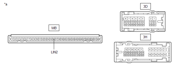
| *a | Component without harness connected (Instrument Panel Junction Block Assembly) | - | - |
(b) Remove the main body ECU (multiplex network body ECU) from the instrument panel junction block assembly.
(c) Measure the resistance according to the value(s) in the table below.
HINT:
This inspection is to check the LIN communication line in the instrument panel junction block assembly that connects the wire harness to the built-in main body ECU (multiplex network body ECU).
Standard Resistance:
| Tester Connection | Condition | Specified Condition |
|---|---|---|
| 3D-17 or 3H-25 - MB-16 (LIN2) | Always | Below 1 Ω |
| OK | | REPLACE MAIN BODY ECU (MULTIPLEX NETWORK BODY ECU) |
| NG | | REPLACE INSTRUMENT PANEL JUNCTION BLOCK ASSEMBLY |
| 4. | INSPECT INSTRUMENT PANEL JUNCTION BLOCK ASSEMBLY |
(a) Remove the instrument panel junction block assembly.
Click here
| *a | Component without harness connected (Instrument Panel Junction Block Assembly) | - | - |
(b) Remove the main body ECU (multiplex network body ECU) from the instrument panel junction block assembly.
(c) Measure the resistance according to the value(s) in the table below.
HINT:
This inspection is to check the LIN communication line in the instrument panel junction block assembly that connects the wire harness to the built-in main body ECU (multiplex network body ECU).
Standard Resistance:
| Tester Connection | Condition | Specified Condition |
|---|---|---|
| 3H-25 - MB-16 (LIN2) | Always | Below 1 Ω |
| NG | | REPLACE INSTRUMENT PANEL JUNCTION BLOCK ASSEMBLY |
|
| 5. | CHECK HARNESS AND CONNECTOR (INSTRUMENT PANEL JUNCTION BLOCK ASSEMBLY - MULTIPLEX NETWORK MASTER SWITCH ASSEMBLY) |
(a) Disconnect the 3H instrument panel junction block assembly connector.
(b) Disconnect the J20 multiplex network master switch assembly connector.
(c) Measure the resistance according to the value(s) in the table below.
NOTICE:
Make sure that each ECU is in sleep mode before performing the inspection. To enter sleep mode, turn the engine switch from on (IG) to off and wait for 180 seconds or more without operating any switches.
Standard Resistance:
| Tester Connection | Condition | Specified Condition |
|---|---|---|
| 3H-25 - J20-17 (LIN1) | Engine switch off | Below 1 Ω |
| OK | | REPLACE MAIN BODY ECU (MULTIPLEX NETWORK BODY ECU) |
| NG | | REPAIR OR REPLACE HARNESS OR CONNECTOR |
| 6. | CHECK HARNESS AND CONNECTOR (INSTRUMENT PANEL JUNCTION BLOCK ASSEMBLY - POWER WINDOW REGULATOR MOTOR ASSEMBLY (FRONT PASSENGER DOOR)) |
(a) Disconnect the 3H instrument panel junction block assembly connector.
(b) Disconnect the J5 power window regulator motor assembly (front passenger door) connector.
(c) Measure the resistance according to the value(s) in the table below.
NOTICE:
Make sure that each ECU is in sleep mode before performing the inspection. To enter sleep mode, turn the engine switch from on (IG) to off and wait for 180 seconds or more without operating any switches.
Standard Resistance:
| Tester Connection | Condition | Specified Condition |
|---|---|---|
| 3H-25 - J5-9 (LIN) | Engine switch off | Below 1 Ω |
| OK | | REPLACE MAIN BODY ECU (MULTIPLEX NETWORK BODY ECU) |
| NG | | REPAIR OR REPLACE HARNESS OR CONNECTOR |
| 7. | CHECK HARNESS AND CONNECTOR (INSTRUMENT PANEL JUNCTION BLOCK ASSEMBLY - MULTIPLEX NETWORK MASTER SWITCH ASSEMBLY) |
(a) Disconnect the 3H instrument panel junction block assembly connector.
(b) Disconnect the J20 multiplex network master switch assembly connector.
(c) Measure the resistance according to the value(s) in the table below.
NOTICE:
Make sure that each ECU is in sleep mode before performing the inspection. To enter sleep mode, turn the engine switch from on (IG) to off and wait for 180 seconds or more without operating any switches.
Standard Resistance:
| Tester Connection | Condition | Specified Condition |
|---|---|---|
| 3H-25 - J20-17 (LIN1) | Engine switch off | Below 1 Ω |
| OK | | REPLACE MAIN BODY ECU (MULTIPLEX NETWORK BODY ECU) |
| NG | | REPAIR OR REPLACE HARNESS OR CONNECTOR |
| 8. | CHECK HARNESS AND CONNECTOR (MULTIPLEX NETWORK MASTER SWITCH ASSEMBLY - BATTERY AND BODY GROUND) |
(a) Disconnect the J20 multiplex network master switch assembly connector.
(b) Measure the voltage according to the value(s) in the table below.
Standard Voltage:
| Tester Connection | Condition | Specified Condition |
|---|---|---|
| J20-11 (B) - J20-12 (GND) | Always | 11 to 14 V |
(c) Measure the resistance according to the value(s) in the table below.
Standard Resistance:
| Tester Connection | Condition | Specified Condition |
|---|---|---|
| J20-12 (GND) - Body ground | Always | Below 1 Ω |
| NG | | REPAIR OR REPLACE HARNESS OR CONNECTOR |
|
| 9. | CHECK HARNESS AND CONNECTOR (INSTRUMENT PANEL JUNCTION BLOCK ASSEMBLY - MULTIPLEX NETWORK MASTER SWITCH ASSEMBLY) |
(a) Disconnect the 3H instrument panel junction block assembly connector.
(b) Measure the resistance according to the value(s) in the table below.
NOTICE:
Make sure that each ECU is in sleep mode before performing the inspection. To enter sleep mode, turn the engine switch from on (IG) to off and wait for 180 seconds or more without operating any switches.
Standard Resistance:
| Tester Connection | Condition | Specified Condition |
|---|---|---|
| 3H-25 - J20-17 (LIN1) | Engine switch off | Below 1 Ω |
| OK | | REPLACE MULTIPLEX NETWORK MASTER SWITCH ASSEMBLY |
| NG | | REPAIR OR REPLACE HARNESS OR CONNECTOR |
| 10. | INSPECT INSTRUMENT PANEL JUNCTION BLOCK ASSEMBLY |
(a) Remove the instrument panel junction block assembly.
Click here
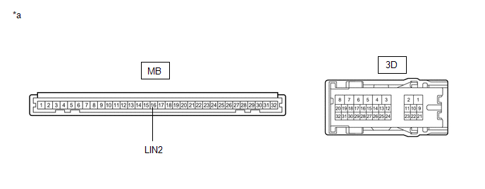
| *a | Component without harness connected (Instrument Panel Junction Block Assembly) | - | - |
(b) Remove the main body ECU (multiplex network body ECU) from the instrument panel junction block assembly.
(c) Measure the resistance according to the value(s) in the table below.
HINT:
This inspection is to check the LIN communication line in the instrument panel junction block assembly that connects the wire harness to the built-in main body ECU (multiplex network body ECU).
Standard Resistance:
| Tester Connection | Condition | Specified Condition |
|---|---|---|
| 3D-17 - MB-16 (LIN2) | Always | Below 1 Ω |
| NG | | REPLACE INSTRUMENT PANEL JUNCTION BLOCK ASSEMBLY |
|
| 11. | CHECK HARNESS AND CONNECTOR (SLIDING ROOF ECU - BATTERY AND BODY GROUND) |
(a) Disconnect the P22 sliding roof ECU (sliding roof drive gear sub-assembly) connector.*1
(b) Disconnect the Q1 sliding roof ECU (sliding roof drive gear assembly) connector.*2
- *1: w/ Sliding Roof System
- *2: w/ Panoramic Moon Roof System
(c) Measure the voltage according to the value(s) in the table below.
Standard Voltage:
w/ Sliding Roof System| Tester Connection | Condition | Specified Condition |
|---|---|---|
| P22-1 (B) - P22-2 (E) | Always | 11 to 14 V |
| Tester Connection | Condition | Specified Condition |
|---|---|---|
| Q1-1 (B) - Q1-2 (E) | Always | 11 to 14 V |
(d) Measure the resistance according to the value(s) in the table below.
Standard Resistance:
w/ Sliding Roof System| Tester Connection | Condition | Specified Condition |
|---|---|---|
| P22-2 (E) - Body ground | Always | Below 1 Ω |
| Tester Connection | Condition | Specified Condition |
|---|---|---|
| Q1-2 (E) - Body ground | Always | Below 1 Ω |
| NG | | REPAIR OR REPLACE HARNESS OR CONNECTOR |
|
| 12. | CHECK HARNESS AND CONNECTOR (INSTRUMENT PANEL JUNCTION BLOCK ASSEMBLY - SLIDING ROOF ECU) |
(a) Measure the resistance according to the value(s) in the table below.
Standard Resistance:
w/ Sliding Roof System| Tester Connection | Condition | Specified Condition |
|---|---|---|
| 3D-17 - P22-7 (MPX1) | Engine switch off | Below 1 Ω |
| Tester Connection | Condition | Specified Condition |
|---|---|---|
| 3D-17 - Q1-7 (MPX1) | Engine switch off | Below 1 Ω |
| Result | Proceed to |
|---|---|
| OK (w/ Sliding Roof System) | A |
| OK (w/ Panoramic Moon Roof System) | B |
| NG | C |
| A | | REPLACE SLIDING ROOF ECU (SLIDING ROOF DRIVE GEAR SUB-ASSEMBLY) |
| B | | REPLACE SLIDING ROOF ECU (SLIDING ROOF DRIVE GEAR ASSEMBLY) |
| C | | REPAIR OR REPLACE HARNESS OR CONNECTOR |
| 13. | CHECK HARNESS AND CONNECTOR (POWER WINDOW REGULATOR MOTOR ASSEMBLY (DRIVER DOOR) - BATTERY AND BODY GROUND) |
(a) Disconnect the J27 power window regulator motor assembly (driver door) connector.
(b) Measure the voltage according to the value(s) in the table below.
Standard Voltage:
| Tester Connection | Condition | Specified Condition |
|---|---|---|
| J27-2 (B) - J27-1 (E) | Always | 11 to 14 V |
(c) Measure the resistance according to the value(s) in the table below.
Standard Resistance:
| Tester Connection | Condition | Specified Condition |
|---|---|---|
| J27-1 (E) - Body ground | Always | Below 1 Ω |
| NG | | REPAIR OR REPLACE HARNESS OR CONNECTOR |
|
| 14. | CHECK HARNESS AND CONNECTOR (INSTRUMENT PANEL JUNCTION BLOCK ASSEMBLY - POWER WINDOW REGULATOR MOTOR ASSEMBLY (DRIVER DOOR)) |
(a) Disconnect the 3H instrument panel junction block assembly connector.
(b) Measure the resistance according to the value(s) in the table below.
NOTICE:
Make sure that each ECU is in sleep mode before performing the inspection. To enter sleep mode, turn the engine switch from on (IG) to off and wait for 180 seconds or more without operating any switches.
Standard Resistance:
| Tester Connection | Condition | Specified Condition |
|---|---|---|
| 3H-25 - J27-9 (LIN) | Always | Below 1 Ω |
| OK | | REPLACE POWER WINDOW REGULATOR MOTOR ASSEMBLY (DRIVER DOOR) |
| NG | | REPAIR OR REPLACE HARNESS OR CONNECTOR |
| 15. | CHECK HARNESS AND CONNECTOR (POWER WINDOW REGULATOR MOTOR ASSEMBLY (FRONT PASSENGER DOOR) - BATTERY AND BODY GROUND) |
(a) Disconnect the J5 power window regulator motor assembly (front passenger door) connector.
(b) Measure the voltage according to the value(s) in the table below.
Standard Voltage:
| Tester Connection | Condition | Specified Condition |
|---|---|---|
| J5-2 (B) - J5-1 (E) | Always | 11 to 14 V |
(c) Measure the resistance according to the value(s) in the table below.
Standard Resistance:
| Tester Connection | Condition | Specified Condition |
|---|---|---|
| J5-1 (E) - Body ground | Always | Below 1 Ω |
| NG | | REPAIR OR REPLACE HARNESS OR CONNECTOR |
|
| 16. | CHECK HARNESS AND CONNECTOR (INSTRUMENT PANEL JUNCTION BLOCK ASSEMBLY - POWER WINDOW REGULATOR MOTOR ASSEMBLY (FRONT PASSENGER DOOR)) |
(a) Disconnect the 3H instrument panel junction block assembly connector.
(b) Measure the resistance according to the value(s) in the table below.
NOTICE:
Make sure that each ECU is in sleep mode before performing the inspection. To enter sleep mode, turn the engine switch from on (IG) to off and wait for 180 seconds or more without operating any switches.
Standard Resistance:
| Tester Connection | Condition | Specified Condition |
|---|---|---|
| 3H-25 - J5-9 (LIN) | Engine switch off | Below 1 Ω |
| OK | | REPLACE POWER WINDOW REGULATOR MOTOR ASSEMBLY (FRONT PASSENGER DOOR) |
| NG | | REPAIR OR REPLACE HARNESS OR CONNECTOR |
| 17. | CHECK HARNESS AND CONNECTOR (POWER WINDOW REGULATOR MOTOR ASSEMBLY (REAR RH DOOR) - BATTERY AND BODY GROUND) |
(a) Disconnect the L4 power window regulator motor assembly (rear RH door) connector.
(b) Measure the voltage according to the value(s) in the table below.
Standard Voltage:
| Tester Connection | Condition | Specified Condition |
|---|---|---|
| L4-2 (B) - L4-1 (E) | Always | 11 to 14 V |
(c) Measure the resistance according to the value(s) in the table below.
Standard Resistance:
| Tester Connection | Condition | Specified Condition |
|---|---|---|
| L4-1 (E) - Body ground | Always | Below 1 Ω |
| NG | | REPAIR OR REPLACE HARNESS OR CONNECTOR |
|
| 18. | CHECK HARNESS AND CONNECTOR (INSTRUMENT PANEL JUNCTION BLOCK ASSEMBLY - POWER WINDOW REGULATOR MOTOR ASSEMBLY (REAR RH DOOR)) |
(a) Disconnect the 3H instrument panel junction block assembly connector.
(b) Measure the resistance according to the value(s) in the table below.
NOTICE:
Make sure that each ECU is in sleep mode before performing the inspection. To enter sleep mode, turn the engine switch from on (IG) to off and wait for 180 seconds or more without operating any switches.
Standard Resistance:
| Tester Connection | Condition | Specified Condition |
|---|---|---|
| 3H-25 - L4-9 (LIN) | Engine switch off | Below 1 Ω |
| OK | | REPLACE POWER WINDOW REGULATOR MOTOR ASSEMBLY (REAR RH DOOR) |
| NG | | REPAIR OR REPLACE HARNESS OR CONNECTOR |
| 19. | CHECK HARNESS AND CONNECTOR (POWER WINDOW REGULATOR MOTOR ASSEMBLY (REAR LH DOOR) - BATTERY AND BODY GROUND) |
(a) Disconnect the L10 power window regulator motor assembly (rear LH door) connector.
(b) Measure the voltage according to the value(s) in the table below.
Standard Voltage:
| Tester Connection | Condition | Specified Condition |
|---|---|---|
| L10-2 (B) - L10-1 (E) | Always | 11 to 14 V |
(c) Measure the resistance according to the value(s) in the table below.
Standard Resistance:
| Tester Connection | Condition | Specified Condition |
|---|---|---|
| L10-1 (E) - Body ground | Always | Below 1 Ω |
| NG | | REPAIR OR REPLACE HARNESS OR CONNECTOR |
|
| 20. | CHECK HARNESS AND CONNECTOR (INSTRUMENT PANEL JUNCTION BLOCK ASSEMBLY - POWER WINDOW REGULATOR MOTOR ASSEMBLY (REAR LH DOOR)) |
(a) Disconnect the 3H instrument panel junction block assembly connector.
(b) Measure the resistance according to the value(s) in the table below.
NOTICE:
Make sure that each ECU is in sleep mode before performing the inspection. To enter sleep mode, turn the engine switch from on (IG) to off and wait for 180 seconds or more without operating any switches.
Standard Resistance:
| Tester Connection | Condition | Specified Condition |
|---|---|---|
| 3H-25 - L10-9 (LIN) | Engine switch off | Below 1 Ω |
| OK | | REPLACE POWER WINDOW REGULATOR MOTOR ASSEMBLY (REAR LH DOOR) |
| NG | | REPAIR OR REPLACE HARNESS OR CONNECTOR |
READ NEXT:
 Diagnostic Trouble Code Chart
DIAGNOSTIC TROUBLE CODE CHART LIN Communication System DTC No. Detection Item Link B1206 P/W Master Switch Communication Stop B1273 Sliding Roof ECU Communication Stop
Data List / Active Test
DATA LIST / ACTIVE TEST DATA LIST HINT: Using the Techstream to read the Data List allows the values or states of switches, sensors, actuators and other items to be read without removing any parts. Th
Dtc Check / Clear
DTC CHECK / CLEAR CHECK DTC (a) Connect the Techstream to the DLC3. (b) Turn the engine switch on (IG). (c) Turn the Techstream on. (d) Enter the following menus: Body Electrical / Main Body or Smart
SEE MORE:
Inspection
INSPECTION PROCEDURE 1. INSPECT FUEL PUMP ASSEMBLY (a) Measure the resistance according to the value(s) in the table below. Standard Resistance: Tester Connection Condition Specified Condition 1 - 2 20°C (68°F) 0.45 to 0.55 Ω If the result is not as specified, replace the fu
System Description
SYSTEM DESCRIPTION GENERAL (a) The blind spot monitor system has a blind spot monitor function. (1) Blind spot monitor function
The blind spot monitor function is a function that assists the driver when changing lanes.
This function uses quasi-millimeter wave radar to detect vehicles that are tra
