Lexus ES: Camshaft Oil Control Valve
Components
COMPONENTS
ILLUSTRATION
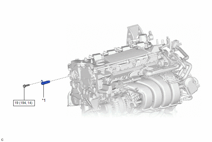
| *1 | CAMSHAFT TIMING VALVE ASSEMBLY | - | - |
.png) | N*m (kgf*cm, ft.*lbf): Specified torque | - | - |
On-vehicle Inspection
ON-VEHICLE INSPECTION
PROCEDURE
1. REMOVE CAM TIMING OIL CONTROL SOLENOID ASSEMBLY
Click here .gif)
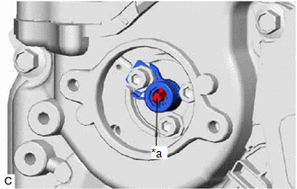
2. INSPECT CAMSHAFT TIMING VALVE ASSEMBLY
| (a) Check the stroke of the plunger in the center of the camshaft timing valve assembly. Standard Stroke: 2.2 mm (0.0866 in.) or more If the result is not as specified, replace the camshaft timing valve assembly. |
|
3. INSTALL CAM TIMING OIL CONTROL SOLENOID ASSEMBLY
Click here
Removal
REMOVAL
CAUTION / NOTICE / HINT
NOTICE:
This procedure includes the removal of small-head bolts. Refer to Small-Head Bolts of Basic Repair Hint to identify the small-head bolts.
Click here .gif)
PROCEDURE
1. REMOVE CAM TIMING OIL CONTROL SOLENOID ASSEMBLY
Click here
2. REMOVE CAMSHAFT TIMING VALVE ASSEMBLY
| (a) Using a 5 mm hexagon socket wrench, remove the bolt. NOTICE: Do not remove the other 2 bolts. HINT: If it is difficult to loosen the bolt due to the tools contacting the vehicle body or other parts, rotate the crankshaft to move the bolt to a position where it can be removed easily. |
|
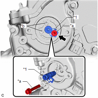
(b) Remove the camshaft timing valve assembly from the camshaft timing exhaust gear assembly.
Installation
INSTALLATION
CAUTION / NOTICE / HINT
NOTICE:
This procedure includes the installation of small-head bolts. Refer to Small-Head Bolts of Basic Repair Hint to identify the small-head bolts.
Click here .gif)
PROCEDURE
1. INSTALL CAMSHAFT TIMING VALVE ASSEMBLY
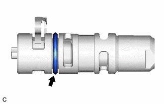
| (a) Apply a light coat of engine oil to the O-ring of the camshaft timing valve assembly. NOTICE: If reusing the camshaft timing valve assembly, be sure to inspect the O-ring. |
|
(b) Temporarily install the camshaft timing valve assembly to the camshaft timing exhaust gear assembly.
NOTICE:
If the camshaft timing valve assembly has been struck or dropped, replace it.
(c) Using a 5 mm hexagon socket wrench, install the camshaft timing valve assembly with the bolt.
Torque:
19 N·m {194 kgf·cm, 14 ft·lbf}
2. INSTALL CAM TIMING OIL CONTROL SOLENOID ASSEMBLY
Click here
READ NEXT:
 Removal
REMOVAL CAUTION / NOTICE / HINT NOTICE: This procedure includes the removal of small-head bolts. Refer to Small-Head Bolts of Basic Repair Hint to identify the small-head bolts. Click here PROCEDURE
Installation
INSTALLATION CAUTION / NOTICE / HINT NOTICE: This procedure includes the installation of small-head bolts. Refer to Small-Head Bolts of Basic Repair Hint to identify the small-head bolts. Click here
SEE MORE:
Starter Relay Circuit Short to Battery (P061512)
MONITOR DESCRIPTION While the engine is being cranked, positive battery voltage is applied to terminal STA of the ECM. If the ECM detects the starter control (STA) signal while the vehicle is being driven, it determines that there is a malfunction in the STA circuit. The ECM then illuminates the MIL
Driver Side Power Window does not Operate with Power Window Master Switch
DESCRIPTION When the power switch is on (IG), the power window regulator motor assembly (for driver door) is operated by the multiplex network master switch assembly. The power window regulator motor assembly (for driver door) has motor, regulator and ECU functions. WIRING DIAGRAM CAUTION / NOTICE
