Lexus ES: On-vehicle Inspection
ON-VEHICLE INSPECTION
PROCEDURE
1. INSPECT STOP LIGHT SWITCH ASSEMBLY
| (a) Disconnect the A80 stop light switch assembly connector. |
|
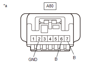
(b) Measure the voltage and resistance on the wire harness side connector according to the value(s) in the table below.
Standard Voltage:
| Tester Connection | Condition | Specified Condition |
|---|---|---|
|
*1: for HV Model
*2: for Gasoline Model | ||
| A80-7 (B) - A80-2 (GND) | Always | 11 to 14 V |
| A80-6 (B) - A80-2 (GND) | Power switch on (IG)*1 | 11 to 14 V |
| Engine switch on (IG)*2 | ||
Standard Resistance:
| Tester Connection | Condition | Specified Condition |
|---|---|---|
| A80-2 (GND) - Body ground | Always | Below 1 Ω |
If the result is not as specified, repair or replace the wire harness or connector.
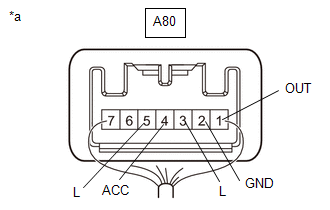
(c) Connect A80 the stop light switch assembly connector.
| (d) Measure the voltage according to the value(s) in the table below. Standard Voltage:
If the result is not as specified, replace the stop light switch assembly. |
| |||||||||||||||||||||||||||||||||||||
READ NEXT:
 Removal
REMOVAL PROCEDURE 1. REMOVE NO. 1 INSTRUMENT PANEL UNDER COVER SUB-ASSEMBLY Click here 2. REMOVE STOP LIGHT SWITCH ASSEMBLY (a) Disconnect the connector. (b) Turn the stop light swit
Installation
INSTALLATION PROCEDURE 1. INSTALL STOP LIGHT SWITCH ASSEMBLY (a) Insert the stop light switch assembly until the threaded sleeve hits the pedal as shown in the illustration. *1 Stop Light Switch
SEE MORE:
Rain Sensor Malfunction (B1400)
DESCRIPTION This DTC is stored when the rain sensor detects an internal malfunction. DTC No. Detection Item DTC Detection Condition Trouble Area Memory DTC Output from B1400 Rain Sensor Malfunction
IG power source voltage is 9.5 V or more
Either of the following is dete
DCM System Internal Failure (B15A804)
DESCRIPTION This DTC is stored when an internal circuit malfunction is detected by the DCM (telematics transceiver) self check. DTC No. Detection Item DTC Detection Condition Trouble Area B15A804 DCM System Internal Failure DCM (telematics transceiver) internal malfunction DCM (te
