Lexus ES: Installation
INSTALLATION
CAUTION / NOTICE / HINT
NOTICE:
Make sure to hold the front wiper arm while lifting it, as lifting the front wiper arm by the front wiper blade may damage or deform the front wiper blade.
PROCEDURE
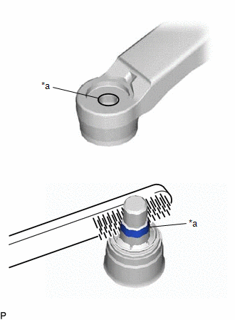
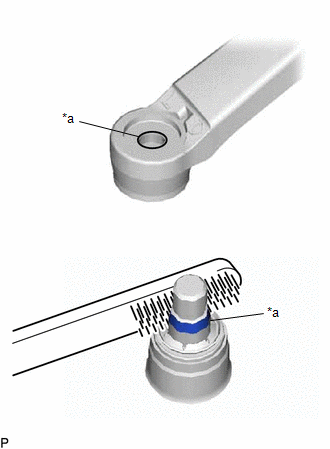
1. INSTALL WINDSHIELD WIPER MOTOR ASSEMBLY
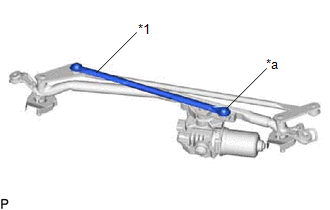
(a) Using a T30 "TORX" socket wrench, install the windshield wiper motor assembly to the wiper link assembly with the 2 bolts.
Torque:
7.5 N·m {76 kgf·cm, 66 in·lbf}
| (b) Apply MP grease to the pivot of the windshield wiper motor assembly. |
|
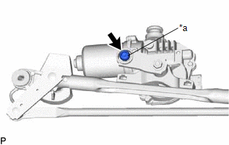
| (c) Connect the No. 1 wiper link rod to the pivot of the windshield wiper motor assembly. |
|
2. INSTALL WINDSHIELD WIPER MOTOR AND LINK ASSEMBLY
(a) Install the windshield wiper motor and link assembly as shown in the illustration.
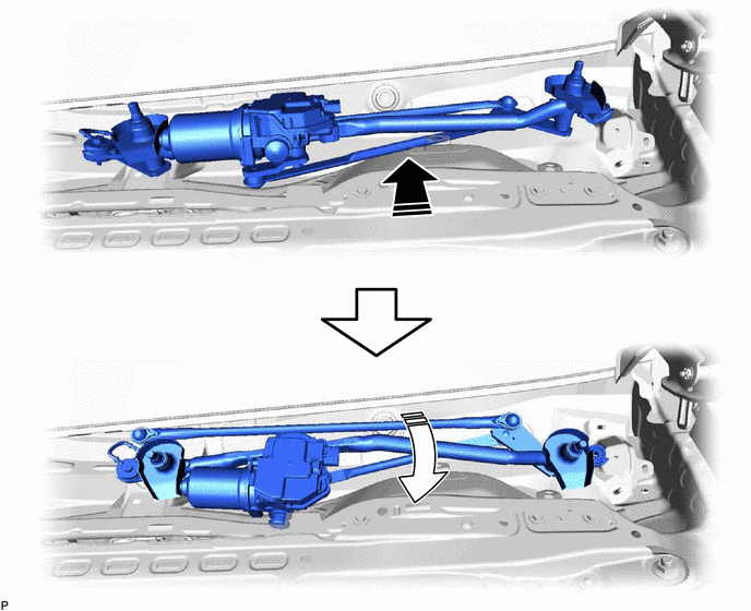
.png) | Install in this Direction (1) | .png) | Install in this Direction (2) |
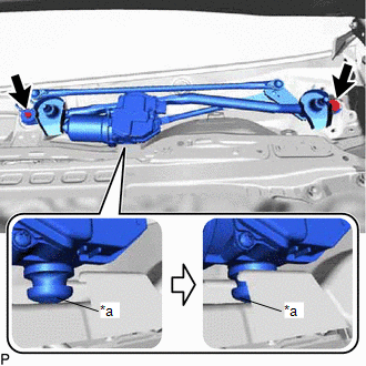
| (b) Engage the motor grommet as shown in the illustration. NOTICE: Be careful not to damage the windshield glass when installing the windshield wiper motor and link assembly. |
|
(c) Install the windshield wiper motor and link assembly with the 2 bolts.
Torque:
7.5 N·m {76 kgf·cm, 66 in·lbf}
HINT:
Tighten the bolts in the order shown in the illustration.
(d) Connect the connector.
(e) Engage the 2 clamps.
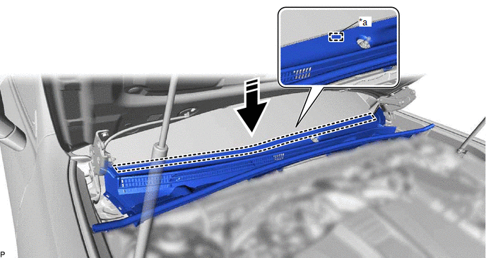
3. INSTALL COWL TOP VENTILATOR LOUVER SUB-ASSEMBLY
(a) Insert the cowl top ventilator louver sub-assembly as shown in the illustration.

| | Install in this Direction | - | - |
NOTICE:
Make sure that the cowl top ventilator louver sub-assembly does not contact the vehicle body, otherwise it may be damaged.
(b) Engage the guide as shown in the illustration.
| *a | Guide | - | - |
| | Install in this Direction | - | - |
NOTICE:
Make sure to engage the guide securely, otherwise the cowl top ventilator louver sub-assembly may pop up when engaging it to the windshield glass.
(c) Engage the 4 claws to install the cowl top ventilator louver sub-assembly as shown in the illustration.
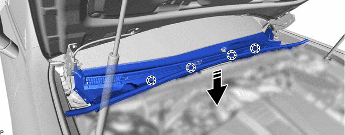
| | Install in this Direction | - | - |
4. CONNECT WINDSHIELD OUTSIDE MOULDING LH
| (a) Engage the claw to connect the windshield outside moulding LH. |
|
.png)
5. CONNECT WINDSHIELD OUTSIDE MOULDING RH
| (a) Engage the claw to connect the windshield outside moulding RH. |
|
.png)
6. INSTALL NO. 3 COWL TOP PANEL INSULATOR
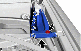
| | Install in this Direction |
(a) Engage the 4 claws as shown in the illustration.
(b) Install the No. 3 cowl top panel insulator with the clip.
(c) Engage the 2 clips to connect the cowl top ventilator louver sub-assembly.
7. INSTALL NO. 2 COWL TOP PANEL INSULATOR
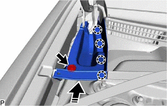
| | Install in this Direction |
(a) Engage the 4 claws as shown in the illustration.
(b) Install the No. 2 cowl top panel insulator with the clip.
(c) Engage the 2 clips to connect the cowl top ventilator louver sub-assembly.
8. INSTALL FRONT WIPER ARM AND BLADE ASSEMBLY RH
(a) When reusing the front wiper arm and blade assembly RH:
| (1) Clean the wiper arm serrations to remove any burrs, dirt, etc. NOTICE: Do not grind down the wiper arm serrations. |
|
(b) When reusing the windshield wiper motor and link assembly:
(1) Clean the wiper pivot serrations with a wire brush.
(c) Turn the engine switch (for Gasoline Model) or power switch (for HV Model) on (IG).
(d) Operate the windshield wiper motor assembly and stop the windshield wiper motor and link assembly at the automatic stop position.
(e) Turn the engine switch (for Gasoline Model) or power switch (for HV Model) off.
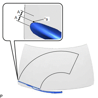
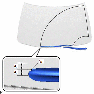
| (f) Install the front wiper arm and blade assembly RH with the nut to the position shown in the illustration. Torque: 22 N·m {224 kgf·cm, 16 ft·lbf} HINT: Hold the wiper arm by hand while tightening the nut. Reference Measurement:
|
|
9. INSTALL FRONT WIPER ARM AND BLADE ASSEMBLY LH
(a) When reusing the front wiper arm and blade assembly LH:
| (1) Clean the wiper arm serrations to remove any burrs, dirt, etc. NOTICE: Do not grind down the wiper arm serrations. |
|
(b) When reusing the windshield wiper motor and link assembly:
(1) Clean the wiper pivot serrations with a wire brush.
| (c) Install the front wiper arm and blade assembly LH with the nut to the position shown in the illustration. Torque: 22 N·m {224 kgf·cm, 16 ft·lbf} HINT: Hold the wiper arm by hand while tightening the nut. Reference Measurement:
|
|
(d) Turn the engine switch (for Gasoline Model) or power switch (for HV Model) on (IG).
(e) Operate the windshield wipers while spraying washer fluid onto the windshield glass. Make sure that the windshield wipers function properly and the wipers do not contact the vehicle body.
(f) Turn the engine switch (for Gasoline Model) or power switch (for HV Model) off.
(g) Lift each wiper arm twice after the wipers stop and check the wiper set position.
10. INSTALL FRONT WIPER ARM HEAD CAP
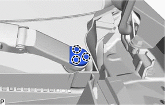
| (a) Engage the 3 claws to install the front wiper arm head cap. HINT: Use the same procedure for the RH side and LH side. |
|
READ NEXT:
 Front Wiper Rubber
ComponentsCOMPONENTS ILLUSTRATION *1 FRONT WIPER BLADE *2 WIPER RUBBER *3 FRONT WIPER RUBBER BACKING PLATE - - ReplacementREPLACEMENT CAUTION / NOTICE / HINT NOTICE: Make sure
Components
COMPONENTS ILLUSTRATION *1 RAIN SENSOR *2 RAIN SENSOR COVER *3 RAIN SENSOR TAPE - -
SEE MORE:
Collision detected or Collision Sensor Connection (Open) (P160600,P160604)
DTC SUMMARY MALFUNCTION DESCRIPTION The hybrid vehicle control ECU and airbag ECU assembly detect that a collision has occurred and shut off the system main relay. The cause of this DTC may be one of the following:
Collision is detected
Detection sensor system malfunction
Airbag system malfu
Position Initialization Incomplete (B2343)
DESCRIPTION This DTC is stored when the sliding roof ECU (sliding roof drive gear sub-assembly) has not been initialized. DTC No. Detection Item DTC Detection Condition Trouble Area B2343 Position Initialization Incomplete Sliding roof ECU (sliding roof drive gear sub-assembly) has
