
Lexus ES: On-vehicle Inspection
Lexus ES (XZ10) Service Manual / Engine & Hybrid System / A25a-fxs (engine Control) / Camshaft Oil Control Valve / On-vehicle Inspection
ON-VEHICLE INSPECTION
PROCEDURE
1. REMOVE CAM TIMING OIL CONTROL SOLENOID ASSEMBLY
Click here .gif)
2. INSPECT CAMSHAFT TIMING OIL CONTROL VALVE ASSEMBLY (EXHAUST CAMSHAFT TIMING GEAR BOLT ASSEMBLY)
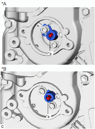
| (a) Check the stroke of the plunger in the center of the camshaft timing oil control valve assembly (exhaust camshaft timing gear bolt assembly). Standard Stroke: 2.2 mm (0.0866 in.) or more If the result is not as specified, replace the camshaft timing oil control valve assembly (exhaust camshaft timing gear bolt assembly). |
|
3. INSTALL CAM TIMING OIL CONTROL SOLENOID ASSEMBLY
Click here
READ NEXT:
 Removal
REMOVAL CAUTION / NOTICE / HINT NOTICE: This procedure includes the removal of small-head bolts. Refer to Small-Head Bolts of Basic Repair Hint to identify the small-head bolts. Click here PROCEDURE
Installation
INSTALLATION CAUTION / NOTICE / HINT NOTICE: This procedure includes the installation of small-head bolts. Refer to Small-Head Bolts of Basic Repair Hint to identify the small-head bolts. Click here
Camshaft Position Sensor
ComponentsCOMPONENTS ILLUSTRATION *1 NO. 1 ENGINE COVER SUB-ASSEMBLY *2 CAMSHAFT POSITION SENSOR (for Intake Side) *3 CAMSHAFT POSITION SENSOR (for Exhaust Side) - - N*m (k
SEE MORE:
Terminals Of Ecu
TERMINALS OF ECU CHECK SLIDING ROOF ECU (SLIDING ROOF DRIVE GEAR ASSEMBLY) (a) Disconnect the Q1 sliding roof ECU (sliding roof drive gear assembly) connector. (b) Measure the resistance and voltage according to the value(s) in the table below. HINT: Measure the values on the wire harness side with
Brake System Malfunction (C13A9)
DESCRIPTION The parking brake ECU (brake actuator assembly) receives the wheel speed signal of each wheel from the skid control ECU (brake booster with master cylinder assembly) via CAN communication. This DTC is stored when a malfunction occurs in the skid control ECU (brake booster with master cyl
© 2016-2026 Copyright www.lexguide.net
