Lexus ES: Camshaft Position Sensor
Components
COMPONENTS
ILLUSTRATION
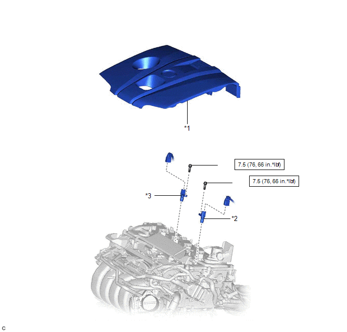
| *1 | NO. 1 ENGINE COVER SUB-ASSEMBLY | *2 | CAMSHAFT POSITION SENSOR (for Intake Side) |
| *3 | CAMSHAFT POSITION SENSOR (for Exhaust Side) | - | - |
.png) | N*m (kgf*cm, ft.*lbf): Specified torque | ● | Non-reusable part |
| ★ | Precoated part | - | - |
Removal
REMOVAL
CAUTION / NOTICE / HINT
NOTICE:
This procedure includes the removal of small-head bolts. Refer to Small-Head Bolts of Basic Repair Hint to identify the small-head bolts.
Click here .gif)
PROCEDURE
1. REMOVE NO. 1 ENGINE COVER SUB-ASSEMBLY
Click here
2. REMOVE CAMSHAFT POSITION SENSOR (for Intake Side)
| (a) Disconnect the camshaft position sensor connector. |
|
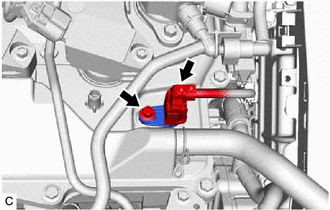
(b) Using an 8 mm socket wrench, remove the bolt and camshaft position sensor from the cylinder head cover sub-assembly.
NOTICE:
If the camshaft position sensor has been struck or dropped, replace it.
3. REMOVE CAMSHAFT POSITION SENSOR (for Exhaust Side)
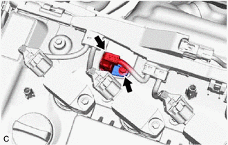
(a) Disconnect the camshaft position sensor connector.
| (b) Using an 8 mm socket wrench, remove the bolt and camshaft position sensor from the cylinder head cover sub-assembly. NOTICE: If the camshaft position sensor has been struck or dropped, replace it. |
|
Installation
INSTALLATION
CAUTION / NOTICE / HINT
NOTICE:
This procedure includes the installation of small-head bolts. Refer to Small-Head Bolts of Basic Repair Hint to identify the small-head bolts.
Click here .gif)
PROCEDURE
1. INSTALL CAMSHAFT POSITION SENSOR (for Exhaust Side)
(a) Apply a light coat of engine oil to the O-ring of the camshaft position sensor.
NOTICE:
If reusing the camshaft position sensor, be sure to inspect the O-ring.
(b) Using an 8 mm socket wrench, install the camshaft position sensor to the cylinder head cover sub-assembly with a new bolt.
Torque:
7.5 N·m {76 kgf·cm, 66 in·lbf}
NOTICE:
- If the camshaft position sensor has been struck or dropped, replace it.
- Make sure that the O-ring is not cracked or moved out of place when installing the camshaft position sensor.
(c) Connect the camshaft position sensor connector.
2. INSTALL CAMSHAFT POSITION SENSOR (for Intake Side)
(a) Apply a light coat of engine oil to the O-ring of the camshaft position sensor.
NOTICE:
If reusing the camshaft position sensor, be sure to inspect the O-ring.
(b) Using an 8 mm socket wrench, install the camshaft position sensor to the cylinder head cover sub-assembly with a new bolt.
Torque:
7.5 N·m {76 kgf·cm, 66 in·lbf}
NOTICE:
- If the camshaft position sensor has been struck or dropped, replace it.
- Make sure that the O-ring is not cracked or moved out of place when installing the camshaft position sensor.
(c) Connect the camshaft position sensor connector.
3. INSPECT FOR ENGINE OIL LEAK
Click here
4. INSTALL NO. 1 ENGINE COVER SUB-ASSEMBLY
Click here
READ NEXT:
 Components
COMPONENTS ILLUSTRATION *1 CAM TIMING CONTROL MOTOR O-RING *2 CAM TIMING CONTROL MOTOR WITH EDU ASSEMBLY *3 NO. 1 ENGINE COVER SUB-ASSEMBLY - - N*m (kgf*cm, ft.*lbf): Specif
On-vehicle Inspection
ON-VEHICLE INSPECTION PROCEDURE 1. INSPECT CAM TIMING CONTROL MOTOR WITH EDU ASSEMBLY (a) Check Rotation Direction Signal: (1) Connect the Techstream to the DLC3. (2) Turn the power switch on (IG). (3
SEE MORE:
Ecm
InstallationINSTALLATION PROCEDURE 1. INSTALL NO. 2 ECM BRACKET (a) Install the No. 2 ECM bracket to the ECM with the 2 screws. Torque: 4.5 N·m {46 kgf·cm, 40 in·lbf} 2. INSTALL NO. 1 ECM BRACKET (a) Install the No. 1 ECM bracket to the ECM with the 2 screws. Torque: 4.5 N·m {46 kgf·cm, 40 i
Remote Control System does not Operate
DESCRIPTION The main body ECU (multiplex network body ECU) receives remote control signals from the driver door key cylinder or electrical key transmitter sub-assembly. Then, the main body ECU (multiplex network body ECU) activates the power window motor and sends the remote control signals to the s
