Lexus ES: On-vehicle Inspection
ON-VEHICLE INSPECTION
CAUTION / NOTICE / HINT
HINT:
Refer to Problem Symptoms Table.
Click here .gif)
PROCEDURE
1. REMOVE FRONT WHEEL OPENING EXTENSION PAD LH
Click here
2. REMOVE FRONT WHEEL OPENING EXTENSION PAD RH
Click here
3. REMOVE NO. 1 ENGINE UNDER COVER
Click here
4. REMOVE NO. 3 ENGINE UNDER COVER
Click here
5. INSPECT FRONT ENGINE MOUNTING INSULATOR
(a) Disconnect the vacuum hose from the front engine mounting insulator.
| (b) Using a vacuum pump, apply vacuum of 80 kPa (600 mmHg, 23.6 in.Hg) and wait for 1 minute. |
|
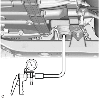
(c) Check that there is no change in the needle movement of the vacuum pump gauge.
OK:
Vacuum pressure holds.
(d) Check that there is no fluid leakage caused by a break in the diaphragm.
(e) Connect the vacuum hose to the front engine mounting insulator.
6. INSTALL NO. 3 ENGINE UNDER COVER
Click here
7. INSTALL NO. 1 ENGINE UNDER COVER
Click here
8. INSTALL FRONT WHEEL OPENING EXTENSION PAD LH
Click here
9. INSTALL FRONT WHEEL OPENING EXTENSION PAD RH
Click here
READ NEXT:
 Removal
REMOVAL PROCEDURE 1. REMOVE VACUUM SWITCHING VALVE (for Active Control Engine Mount System) Click here 2. REMOVE V-BANK COVER SUB-ASSEMBLY Click here 3. REMOVE FRONT WHEEL OPENING EXTENSION PAD
Installation
INSTALLATION PROCEDURE 1. INSTALL FRONT ENGINE MOUNTING INSULATOR (a) Install the stay to the front engine mounting insulator with the nut. Torque: 6.0 N·m {61 kgf·cm, 53 in·lbf} (b) Install the f
SEE MORE:
Dtc Check / Clear
DTC CHECK / CLEAR CHECK DTC (a) Connect the Techstream to the DLC3. (b) Turn the power switch on (IG). (c) Turn the Techstream on. (d) Enter the following menus: Chassis > Front Recognition Camera > Trouble Codes (e) Check for DTCs (Test Failed / Pending / Confirmed). Techstream Display D
Inspection
INSPECTION PROCEDURE 1. INSPECT FRONT DRIVE SHAFT ASSEMBLY (a) Check that there is no excessive play in the radial direction of the outboard joint. (b) Check that the inboard joint slides smoothly in the thrust direction. (c) Check that there is no excessive play in the radial directi
