Lexus ES: Mute Signal Circuit between Stereo Component Amplifier and Telematics Transceiver
DESCRIPTION
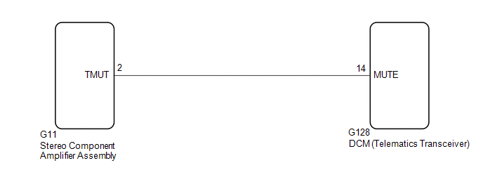
The DCM (telematics transceiver) sends a mute signal to the stereo component amplifier assembly.
The stereo component amplifier assembly controls the volume according to the mute signal from the DCM (telematics transceiver).
WIRING DIAGRAM
CAUTION / NOTICE / HINT
NOTICE:
-
Depending on the parts that are replaced during vehicle inspection or maintenance, performing initialization, registration or calibration may be needed. Refer to Precaution for Audio and Visual System.
Click here
.gif)
-
Before replacing the DCM (telematics transceiver), refer to Registration.
Click here
PROCEDURE
| 1. | INSPECT DCM (TELEMATICS TRANSCEIVER) |
| (a) Measure the voltage according to the value(s) in the table below. Standard Voltage:
|
|
| OK |  | PROCEED TO NEXT SUSPECTED AREA SHOWN IN PROBLEM SYMPTOMS TABLE |
|

| 2. | CHECK HARNESS AND CONNECTOR (STEREO COMPONENT AMPLIFIER ASSEMBLY - DCM (TELEMATICS TRANSCEIVER)) |
(a) Disconnect the G11 stereo component amplifier assembly connector.
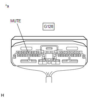
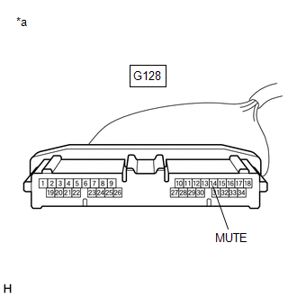
(b) Disconnect the G128 DCM (telematics transceiver) connector.
(c) Measure the resistance according to the value(s) in the table below.
Standard Resistance:
| Tester Connection | Condition | Specified Condition |
|---|---|---|
| G11-2 (TMUT) - G128-14 (MUTE) | Always | Below 1 Ω |
| G11-2 (TMUT) or G128-14 (MUTE) - Body ground | Always | 10 kΩ or higher |
| NG | | REPAIR OR REPLACE HARNESS AND CONNECTOR |
|
| 3. | INSPECT STEREO COMPONENT AMPLIFIER ASSEMBLY |
(a) Reconnect the G11 stereo component amplifier assembly connector.
| (b) Measure the voltage according to the value(s) in the table below. Standard Voltage:
|
|
| OK | | REPLACE DCM (TELEMATICS TRANSCEIVER) |
| NG | | REPLACE STEREO COMPONENT AMPLIFIER ASSEMBLY |
READ NEXT:
 No Sound can be Heard from Speakers
PROCEDURE 1. CHECK AUDIO SETTINGS (a) In sound output setting mode, set volume, fader and balance to the initial values and check that the sound is normal. OK: Audio system returns to normal
Noise Occurs or Sound Skips when Portable Player Plays
CAUTION / NOTICE / HINT HINT:
Perform this check with the portable player volume set at an appropriate level.
Make sure that there are no obstructions between the portable player and radio receiv
Noise Occurs
PROCEDURE 1. CHECK NOISE CONDITION (a) Check from which direction the noise comes (front left or right, or rear left or right). OK: The location of the noise source can be determined. NG
SEE MORE:
Problem Symptoms Table
PROBLEM SYMPTOMS TABLE Hybrid Control System Symptom Suspected Area Link Cannot enter EV drive mode CAN Communication System Pattern Select Switch EV Mode Circuit EV mode switch Combination meter assembly EV mode indicator light does not illuminate
Parts Location
PARTS LOCATION ILLUSTRATION *1 GENERATOR ASSEMBLY *2 ECM *3 NO. 1 ENGINE ROOM RELAY BLOCK AND NO. 1 JUNCTION BLOCK ASSEMBLY - - ILLUSTRATION *1 COMBINATION METER ASSEMBLY - -
