Lexus ES: Multi-axis Acceleration Sensor Module "A" Supply Voltage Circuit Voltage Out of Range (C14D71C)
DESCRIPTION
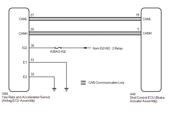
The airbag ECU assembly has a built-in yaw rate and acceleration sensor and detects the vehicle condition.
This DTC is stored when the skid control ECU (brake actuator assembly) receives a sensor supply voltage malfunction signal from the yaw rate and acceleration sensor (airbag ECU assembly).
| DTC No. | Detection Item | DTC Detection Condition | Trouble Area |
|---|---|---|---|
| C14D71C | Multi-axis Acceleration Sensor Module "A" Supply Voltage Circuit Voltage Out of Range | Vehicle speed is 6 km/h (4 mph) or more and yaw rate and acceleration sensor power supply malfunction signal is received for 1 second or more. |
|
WIRING DIAGRAM
CAUTION / NOTICE / HINT
NOTICE:
- Inspect the fuses for circuits related to this system before performing the following procedure.
-
After replacing or reinstalling the yaw rate and acceleration sensor (airbag ECU assembly), perform acceleration sensor zero point calibration and store system information memorization after performing "Reset Memory".
Click here
.gif)
-
When removing/installing a supplemental restraint systems related component, disconnect the cable from the negative (-) battery terminal before performing the procedure.
Click here
PROCEDURE
| 1. | CHECK HARNESS AND CONNECTOR (POWER SOURCE TERMINAL) |
| (a) Turn the engine switch off. |
|
(b) Disconnect the cable from the negative (-) battery terminal.
CAUTION:
Wait at least 90 seconds after disconnecting the cable from the negative (-) battery terminal to disable the SRS system.
Click here
(c) Make sure that there is no looseness at the locking part and the connecting part of the connector.
OK:
The connector is securely connected.
(d) Disconnect the G64 yaw rate and acceleration sensor (airbag ECU assembly) connector.
(e) Check both the connector case and the terminals for deformation and corrosion.
OK:
No deformation or corrosion.
(f) Connect the cable to the negative (-) battery terminal.
(g) Turn the engine switch on (IG).
(h) Operate all the components of the electrical system (defogger, wipers, headlights, heater blower, etc.).
(i) Measure the voltage according to the value(s) in the table below.
Standard Voltage:
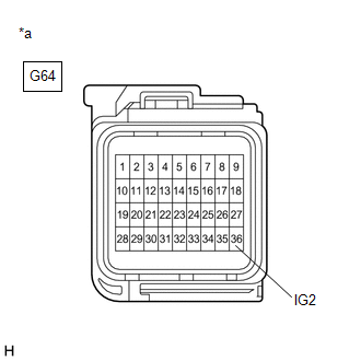
| Tester Connection | Condition | Specified Condition |
|---|---|---|
| G64-36 (IG2) - Body ground | Engine switch on (IG) | 8 to 16 V |
| NG |  | REPAIR OR REPLACE HARNESS OR CONNECTOR (POWER SOURCE CIRCUIT) |
|

| 2. | CHECK HARNESS AND CONNECTOR (GROUND TERMINAL) |
| (a) Turn the engine switch off. |
|
(b) Disconnect the cable from the negative (-) battery terminal.
CAUTION:
Wait at least 90 seconds after disconnecting the cable from the negative (-) battery terminal to disable the SRS system.
Click here
(c) Make sure that there is no looseness at the locking part and the connecting part of the connector.
OK:
The connector is securely connected.
(d) Disconnect the G64 yaw rate and acceleration sensor (airbag ECU assembly) connector.
(e) Check both the connector case and the terminals for deformation and corrosion.
OK:
No deformation or corrosion.
(f) Measure the resistance according to the value(s) in the table below.
Standard Resistance:
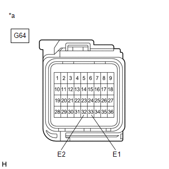
| Tester Connection | Condition | Specified Condition |
|---|---|---|
| G64-33 (E1) - Body ground | Always | Below 1 Ω |
| G64-32 (E2) - Body ground | Always | Below 1 Ω |
| OK | | REPLACE AIRBAG ECU ASSEMBLY |
| NG | | REPAIR OR REPLACE HARNESS OR CONNECTOR (GROUND CIRCUIT) |
READ NEXT:
 Left Front Wheel Speed Sensor Supply Voltage Circuit Short to Ground or Open (C14E014)
DESCRIPTION Refer to DTC C050012 Click here DTC No. Detection Item DTC Detection Condition Trouble Area C14E014 Left Front Wheel Speed Sensor Supply Voltage Circuit Short to Ground or
Right Front Wheel Speed Sensor Supply Voltage Circuit Short to Ground or Open (C14E314)
DESCRIPTION Refer to DTC C050612 Click here DTC No. Detection Item DTC Detection Condition Trouble Area C14E314 Right Front Wheel Speed Sensor Supply Voltage Circuit Short to Ground o
Left Rear Wheel Speed Sensor Supply Voltage Circuit Short to Ground or Open (C14E614)
DESCRIPTION Refer to DTC C050C12 Click here DTC No. Detection Item DTC Detection Condition Trouble Area C14E614 Left Rear Wheel Speed Sensor Supply Voltage Circuit Short to Ground or
SEE MORE:
Random/Multiple Cylinder Misfire Detected (P030000,P030027,P030085-P030600)
DESCRIPTION When the engine misfires, high concentrations of hydrocarbons (HC) enter the exhaust gas. Extremely high hydrocarbon concentration levels can cause an increase in exhaust emission levels. Extremely high concentrations of hydrocarbons can also cause increases in the three-way catalytic co
Engine Coolant Temperature/Engine Oil Temperature Signal Compare Failure (P012F62)
DESCRIPTION The engine is equipped with an engine coolant temperature sensor and an engine oil temperature sensor. The engine coolant temperature sensor and engine oil temperature sensor each have a built-in thermistor. As the temperature decreases, the thermistor resistance increases and as the tem
