Lexus ES: Left Rear Wheel Speed Sensor Supply Voltage Circuit Short to Ground or Open (C14E614)
DESCRIPTION
Refer to DTC C050C12
Click here .gif)
| DTC No. | Detection Item | DTC Detection Condition | Trouble Area |
|---|---|---|---|
| C14E614 | Left Rear Wheel Speed Sensor Supply Voltage Circuit Short to Ground or Open | An open or short in the speed sensor power supply circuit is detected for 0.12 seconds or more. |
|
| Vehicle Condition | |||
|---|---|---|---|
| Pattern 1 | Pattern 2 | ||
| Diagnosis Condition | - | - | - |
| Malfunction Status | An open in the speed sensor power supply circuit is detected. | ○ | - |
| A short in the speed sensor power supply circuit is detected. | - | ○ | |
| Detection Time | 0.12 seconds or more. | 0.12 seconds or more. | |
| Number of Trips | 1 trip | 1 trip | |
HINT:
DTC will be output when conditions for either of the patterns in the table above are met.
WIRING DIAGRAM
Refer to DTC C050C12.
Click here
CAUTION / NOTICE / HINT
NOTICE:
-
After replacing the skid control ECU (brake actuator assembly), perform acceleration sensor zero point calibration and store system information memorization.
Click here
-
After replacing or removing and installing a speed sensor, perform Dealer Mode (Signal Check) inspection to confirm that the speed sensors are operating correctly.
Click here
PROCEDURE
| 1. | CHECK HARNESS AND CONNECTOR (SENSOR POWER SOURCE CIRCUIT) |
| (a) Make sure that there is no looseness at the locking part and the connecting part of the connectors. OK: The connector is securely connected. |
|
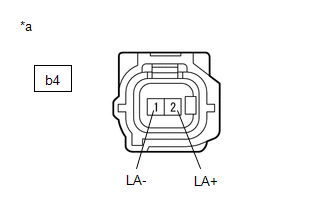
(b) Disconnect the b4 rear speed sensor LH (rear axle hub and bearing assembly LH) connector.
(c) Check both the connector case and the terminals for deformation and corrosion.
OK:
No deformation or corrosion.
(d) Turn the engine switch on (IG).
(e) Measure the voltage according to the value(s) in the table below.
Standard Voltage:
| Tester Connection | Condition | Specified Condition |
|---|---|---|
| b4-2 (LA+) - b4-1 (LA-) | Engine switch on (IG) | 11 to 14 V |
| Result | Proceed to |
|---|---|
| OK | A |
| NG (w/o AVS) | B |
| NG (w/ AVS) | C |
| A |  | REPLACE REAR AXLE HUB AND BEARING ASSEMBLY LH |
| C | | GO TO STEP 4 |
|

| 2. | CHECK HARNESS AND CONNECTOR (SENSOR POWER SOURCE CIRCUIT) |
| (a) Make sure that there is no looseness at the locking part and the connecting part of the connectors. OK: The connector is securely connected. |
|
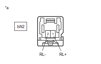
(b) Disconnect the bN2 skid control sensor wire LH (No. 2 parking brake wire assembly) connector.
(c) Check both the connector case and the terminals for deformation and corrosion.
OK:
No deformation or corrosion.
(d) Turn the engine switch on (IG).
(e) Measure the voltage according to the value(s) in the table below.
Standard Voltage:
| Tester Connection | Condition | Specified Condition |
|---|---|---|
| bN2-1 (RL+) - bN2-2 (RL-) | Engine switch on (IG) | 11 to 14 V |
| OK | | REPLACE NO. 2 PARKING BRAKE WIRE ASSEMBLY |
|
| 3. | CHECK HARNESS AND CONNECTOR (NO. 2 PARKING BRAKE WIRE ASSEMBLY - BRAKE ACTUATOR ASSEMBLY) |
(a) Make sure that there is no looseness at the locking part and the connecting part of the connectors.
OK:
The connector is securely connected.
(b) Disconnect the A40 skid control ECU (brake actuator assembly) connector.
(c) Disconnect the bN2 skid control sensor wire LH (No. 2 parking brake wire assembly) connector.
(d) Check both the connector case and the terminals for deformation and corrosion.
OK:
No deformation or corrosion.
(e) Measure the resistance according to the value(s) in the table below.
Standard Resistance:
| Tester Connection | Condition | Specified Condition |
|---|---|---|
| bN2-1 (RL+) or A40-39 (RL+) - Body ground | Always | 10 kΩ or higher |
| OK | | REPLACE BRAKE ACTUATOR ASSEMBLY |
| NG | | REPAIR OR REPLACE HARNESS OR CONNECTOR |
| 4. | CHECK HARNESS AND CONNECTOR (SENSOR POWER SOURCE CIRCUIT) |
| (a) Make sure that there is no looseness at the locking part and the connecting part of the connectors. OK: The connector is securely connected. |
|
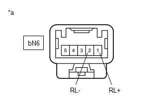
(b) Disconnect the bN6 skid control sensor wire LH (No. 2 parking brake wire assembly) connector.
(c) Check both the connector case and the terminals for deformation and corrosion.
OK:
No deformation or corrosion.
(d) Turn the engine switch on (IG).
(e) Measure the voltage according to the value(s) in the table below.
Standard Voltage:
| Tester Connection | Condition | Specified Condition |
|---|---|---|
| bN6-1 (RL+) - bN6-2 (RL-) | Engine switch on (IG) | 11 to 14 V |
| OK | | REPLACE NO. 2 PARKING BRAKE WIRE ASSEMBLY |
|
| 5. | CHECK HARNESS AND CONNECTOR (NO. 2 PARKING BRAKE WIRE ASSEMBLY - BRAKE ACTUATOR ASSEMBLY) |
(a) Make sure that there is no looseness at the locking part and the connecting part of the connectors.
OK:
The connector is securely connected.
(b) Disconnect the A40 skid control ECU (brake actuator assembly) connector.
(c) Disconnect the bN6 skid control sensor wire LH (No. 2 parking brake wire assembly) connector.
(d) Check both the connector case and the terminals for deformation and corrosion.
OK:
No deformation or corrosion.
(e) Measure the resistance according to the value(s) in the table below.
Standard Resistance:
| Tester Connection | Condition | Specified Condition |
|---|---|---|
| bN6-1 (RL+) or A40-39 (RL+) - Body ground | Always | 10 kΩ or higher |
| OK | | REPLACE BRAKE ACTUATOR ASSEMBLY |
| NG | | REPAIR OR REPLACE HARNESS OR CONNECTOR |
READ NEXT:
 Right Rear Wheel Speed Sensor Supply Voltage Circuit Short to Ground or Open (C14E914)
DESCRIPTION Refer to DTC C051212 Click here DTC No. Detection Item DTC Detection Condition Trouble Area C14E914 Right Rear Wheel Speed Sensor Supply Voltage Circuit Short to Ground or
Brake Pressure Control Solenoid "C" Control Circuit Short to Battery (C14F112,...,C14F149)
DESCRIPTION The ABS solenoid relay and reservoir cut solenoid valves are built into the brake actuator assembly. When the brakes are operating, the reservoir cut solenoid valves supply brake fluid fro
Brake Pressure Control Solenoid "D" Control Circuit Short to Battery (C14FA12,...,C14FA49)
DESCRIPTION The ABS solenoid relay and reservoir cut solenoid valves are built into the brake actuator assembly. When the brakes are operating, the reservoir cut solenoid valves supply brake fluid fro
SEE MORE:
Certification ECU Communication Stop Mode
DESCRIPTION Detection Item Symptom Trouble Area Certification ECU Communication Stop Mode Any of the following conditions are met:
Communication stop for "Certification (Smart)" is indicated on the "Communication Bus Check" screen of the Techstream.
Click here
Communication sto
Rear Television Camera Communication Stop Mode
DESCRIPTION Detection Item Symptom Trouble Area Rear Television Camera Communication Stop Mode Any of the following conditions are met:
Communication stop for "Parking Assist Monitor System / Rear Camera" is indicated on the "Communication Bus Check" screen of the Techstream.
Click h
