Lexus ES: Left Front Wheel Speed Sensor Supply Voltage Circuit Short to Ground or Open (C14E014)
DESCRIPTION
Refer to DTC C050012
Click here .gif)
| DTC No. | Detection Item | DTC Detection Condition | Trouble Area |
|---|---|---|---|
| C14E014 | Left Front Wheel Speed Sensor Supply Voltage Circuit Short to Ground or Open | An open or short in the speed sensor power supply circuit is detected for 0.12 seconds or more. |
|
*: w/ AVS
DTC Detection Conditions: C14E014| Vehicle Condition | |||
|---|---|---|---|
| Pattern 1 | Pattern 2 | ||
| Diagnosis Condition | - | - | - |
| Malfunction Status | An open in the speed sensor power supply circuit is detected. | ○ | - |
| A short in the speed sensor power supply circuit is detected. | - | ○ | |
| Detection Time | 0.12 seconds or more. | 0.12 seconds or more. | |
| Number of Trips | 1 trip | 1 trip | |
HINT:
DTC will be output when conditions for either of the patterns in the table above are met.
WIRING DIAGRAM
Refer to DTC C050012.
Click here
CAUTION / NOTICE / HINT
NOTICE:
-
After replacing the skid control ECU (brake actuator assembly), perform acceleration sensor zero point calibration and store system information memorization.
Click here
-
After replacing or removing and installing a speed sensor, perform Dealer Mode (Signal Check) inspection to confirm that the speed sensors are operating correctly.
Click here
PROCEDURE
| 1. | CHECK VEHICLE |
(a) Check if the vehicle is equipped with AVS.
| Result | Proceed to |
|---|---|
| w/o AVS | A |
| w/ AVS | B |
| B |  | GO TO STEP 4 |
|

| 2. | CHECK HARNESS AND CONNECTOR (SENSOR POWER SOURCE CIRCUIT) |
| (a) Make sure that there is no looseness at the locking part and the connecting part of the connectors. OK: The connector is securely connected. |
|
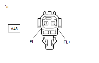
(b) Disconnect the A48 front speed sensor LH connector.
(c) Check both the connector case and the terminals for deformation and corrosion.
OK:
No deformation or corrosion.
(d) Turn the engine switch on (IG).
(e) Measure the voltage according to the value(s) in the table below.
Standard Voltage:
| Tester Connection | Condition | Specified Condition |
|---|---|---|
| A48-1 (FL+) - A48-2 (FL-) | Engine switch on (IG) | 11 to 14 V |
| OK | | REPLACE FRONT SPEED SENSOR LH |
|
| 3. | CHECK HARNESS AND CONNECTOR (FRONT SPEED SENSOR LH - BRAKE ACTUATOR ASSEMBLY) |
(a) Make sure that there is no looseness at the locking part and the connecting part of the connectors.
OK:
The connector is securely connected.
(b) Disconnect the A40 skid control ECU (brake actuator assembly) connector.
(c) Disconnect the A48 front speed sensor LH connector.
(d) Check both the connector case and the terminals for deformation and corrosion.
OK:
No deformation or corrosion.
(e) Measure the resistance according to the value(s) in the table below.
Standard Resistance:
| Tester Connection | Condition | Specified Condition |
|---|---|---|
| A48-1 (FL+) or A40-24 (FL+) - Body ground | Always | 10 kΩ or higher |
| OK | | REPLACE BRAKE ACTUATOR ASSEMBLY |
| NG | | REPAIR OR REPLACE HARNESS OR CONNECTOR |
| 4. | CHECK HARNESS AND CONNECTOR (SENSOR POWER SOURCE CIRCUIT) |
| (a) Make sure that there is no looseness at the locking part and the connecting part of the connectors. OK: The connector is securely connected. |
|
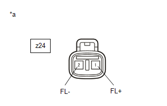
(b) Disconnect the z24 front speed sensor LH connector.
(c) Check both the connector case and the terminals for deformation and corrosion.
OK:
No deformation or corrosion.
(d) Turn the engine switch on (IG).
(e) Measure the voltage according to the value(s) in the table below.
Standard Voltage:
| Tester Connection | Condition | Specified Condition |
|---|---|---|
| z24-1 (FL+) - z24-2 (FL-) | Engine switch on (IG) | 11 to 14 V |
| OK | | REPLACE FRONT SPEED SENSOR LH |
|
| 5. | CHECK HARNESS AND CONNECTOR (SENSOR POWER SOURCE CIRCUIT) |
| (a) Make sure that there is no looseness at the locking part and the connecting part of the connectors. OK: The connector is securely connected. |
|
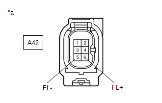
(b) Disconnect the A42 skid control sensor wire with suspension control LH connector.
(c) Check both the connector case and the terminals for deformation and corrosion.
OK:
No deformation or corrosion.
(d) Turn the engine switch on (IG).
(e) Measure the voltage according to the value(s) in the table below.
Standard Voltage:
| Tester Connection | Condition | Specified Condition |
|---|---|---|
| A42-6 (FL+) - A42-5 (FL-) | Engine switch on (IG) | 11 to 14 V |
| OK | | REPLACE SKID CONTROL SENSOR WIRE WITH SUSPENSION CONTROL LH |
|
| 6. | CHECK HARNESS AND CONNECTOR (SKID CONTROL SENSOR WIRE WITH SUSPENSION CONTROL LH - BRAKE ACTUATOR ASSEMBLY) |
(a) Make sure that there is no looseness at the locking part and the connecting part of the connectors.
OK:
The connector is securely connected.
(b) Disconnect the A40 skid control ECU (brake actuator assembly) connector.
(c) Disconnect the A42 skid control sensor wire with suspension control LH connector.
(d) Check both the connector case and the terminals for deformation and corrosion.
OK:
No deformation or corrosion.
(e) Measure the resistance according to the value(s) in the table below.
Standard Resistance:
| Tester Connection | Condition | Specified Condition |
|---|---|---|
| A42-6 (FL+) or A40-24 (FL+) - Body ground | Always | 10 kΩ or higher |
| OK | | REPLACE BRAKE ACTUATOR ASSEMBLY |
| NG | | REPAIR OR REPLACE HARNESS OR CONNECTOR |
READ NEXT:
 Right Front Wheel Speed Sensor Supply Voltage Circuit Short to Ground or Open (C14E314)
DESCRIPTION Refer to DTC C050612 Click here DTC No. Detection Item DTC Detection Condition Trouble Area C14E314 Right Front Wheel Speed Sensor Supply Voltage Circuit Short to Ground o
Left Rear Wheel Speed Sensor Supply Voltage Circuit Short to Ground or Open (C14E614)
DESCRIPTION Refer to DTC C050C12 Click here DTC No. Detection Item DTC Detection Condition Trouble Area C14E614 Left Rear Wheel Speed Sensor Supply Voltage Circuit Short to Ground or
Right Rear Wheel Speed Sensor Supply Voltage Circuit Short to Ground or Open (C14E914)
DESCRIPTION Refer to DTC C051212 Click here DTC No. Detection Item DTC Detection Condition Trouble Area C14E914 Right Rear Wheel Speed Sensor Supply Voltage Circuit Short to Ground or
SEE MORE:
Diagnostic Trouble Code Chart
DIAGNOSTIC TROUBLE CODE CHART Front Camera System DTC No. Detection Item Link C10001C Control Module Internal Temperature Sensor "A" Circuit Circuit Voltage Out of Range C10051C Control Module Internal Temperature Sensor "B" Circuit Circuit Voltage Out of Range C100A
Drive Motor "A" Inverter Stuck On (P0A789E,P1C5D19)
DTC SUMMARY MALFUNCTION DESCRIPTION This DTC indicates that a large current flowed through the motor inverter. The cause of this malfunction may be one of the following: Area Main Malfunction Description Hybrid vehicle transaxle assembly
Open or short circuit in the motor coils
Motor
