Lexus ES: Right Front Wheel Speed Sensor Supply Voltage Circuit Short to Ground or Open (C14E314)
DESCRIPTION
Refer to DTC C050612
Click here .gif)
| DTC No. | Detection Item | DTC Detection Condition | Trouble Area |
|---|---|---|---|
| C14E314 | Right Front Wheel Speed Sensor Supply Voltage Circuit Short to Ground or Open | An open or short in the speed sensor power supply circuit is detected for 0.12 seconds or more. |
|
*: w/ AVS
DTC Detection Conditions: C14E314| Vehicle Condition | |||
|---|---|---|---|
| Pattern 1 | Pattern 2 | ||
| Diagnosis Condition | - | - | - |
| Malfunction Status | An open in the speed sensor power supply circuit is detected. | ○ | - |
| A short in the speed sensor power supply circuit is detected. | - | ○ | |
| Detection Time | 0.12 seconds or more. | 0.12 seconds or more. | |
| Number of Trips | 1 trip | 1 trip | |
HINT:
DTC will be output when conditions for either of the patterns in the table above are met.
WIRING DIAGRAM
Refer to DTC C050612.
Click here
CAUTION / NOTICE / HINT
NOTICE:
-
After replacing the skid control ECU (brake actuator assembly), perform acceleration sensor zero point calibration and store system information memorization.
Click here
-
After replacing or removing and installing a speed sensor, perform Dealer Mode (Signal Check) inspection to confirm that the speed sensors are operating correctly.
Click here
PROCEDURE
| 1. | CHECK VEHICLE |
(a) Check if the vehicle is equipped with AVS.
| Result | Proceed to |
|---|---|
| w/o AVS | A |
| w/ AVS | B |
| B |  | GO TO STEP 4 |
|

| 2. | CHECK HARNESS AND CONNECTOR (SENSOR POWER SOURCE CIRCUIT) |
| (a) Make sure that there is no looseness at the locking part and the connecting part of the connectors. OK: The connector is securely connected. |
|
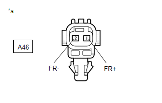
(b) Disconnect the A46 front speed sensor RH connector.
(c) Check both the connector case and the terminals for deformation and corrosion.
OK:
No deformation or corrosion.
(d) Turn the engine switch on (IG).
(e) Measure the voltage according to the value(s) in the table below.
Standard Voltage:
| Tester Connection | Condition | Specified Condition |
|---|---|---|
| A46-1 (FR+) - A46-2 (FR-) | Engine switch on (IG) | 11 to 14 V |
| OK | | REPLACE FRONT SPEED SENSOR RH |
|
| 3. | CHECK HARNESS AND CONNECTOR (FRONT SPEED SENSOR RH - BRAKE ACTUATOR ASSEMBLY) |
(a) Make sure that there is no looseness at the locking part and the connecting part of the connectors.
OK:
The connector is securely connected.
(b) Disconnect the A40 skid control ECU (brake actuator assembly) connector.
(c) Disconnect the A46 front speed sensor RH connector.
(d) Check both the connector case and the terminals for deformation and corrosion.
OK:
No deformation or corrosion.
(e) Measure the resistance according to the value(s) in the table below.
Standard Resistance:
| Tester Connection | Condition | Specified Condition |
|---|---|---|
| A46-1 (FR+) or A40-21 (FR+) - Body ground | Always | 10 kΩ or higher |
| OK | | REPLACE BRAKE ACTUATOR ASSEMBLY |
| NG | | REPAIR OR REPLACE HARNESS OR CONNECTOR |
| 4. | CHECK HARNESS AND CONNECTOR (SENSOR POWER SOURCE CIRCUIT) |
| (a) Make sure that there is no looseness at the locking part and the connecting part of the connectors. OK: The connector is securely connected. |
|
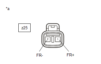
(b) Disconnect the z25 front speed sensor RH connector.
(c) Check both the connector case and the terminals for deformation and corrosion.
OK:
No deformation or corrosion.
(d) Turn the engine switch on (IG).
(e) Measure the voltage according to the value(s) in the table below.
Standard Voltage:
| Tester Connection | Condition | Specified Condition |
|---|---|---|
| z25-1 (FR+) - z25-2 (FR-) | Engine switch on (IG) | 11 to 14 V |
| OK | | REPLACE FRONT SPEED SENSOR RH |
|
| 5. | CHECK HARNESS AND CONNECTOR (SENSOR POWER SOURCE CIRCUIT) |
| (a) Make sure that there is no looseness at the locking part and the connecting part of the connectors. OK: The connector is securely connected. |
|
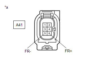
(b) Disconnect the A41 skid control sensor wire with suspension control RH connector.
(c) Check both the connector case and the terminals for deformation and corrosion.
OK:
No deformation or corrosion.
(d) Turn the engine switch on (IG).
(e) Measure the voltage according to the value(s) in the table below.
Standard Voltage:
| Tester Connection | Condition | Specified Condition |
|---|---|---|
| A41-6 (FR+) - A41-5 (FR-) | Engine switch on (IG) | 11 to 14 V |
| OK | | REPLACE SKID CONTROL SENSOR WIRE WITH SUSPENSION CONTROL RH |
|
| 6. | CHECK HARNESS AND CONNECTOR (SKID CONTROL SENSOR WIRE WITH SUSPENSION CONTROL RH - BRAKE ACTUATOR ASSEMBLY) |
(a) Make sure that there is no looseness at the locking part and the connecting part of the connectors.
OK:
The connector is securely connected.
(b) Disconnect the A40 skid control ECU (brake actuator assembly) connector.
(c) Disconnect the A41 skid control sensor wire with suspension control RH connector.
(d) Check both the connector case and the terminals for deformation and corrosion.
OK:
No deformation or corrosion.
(e) Measure the resistance according to the value(s) in the table below.
Standard Resistance:
| Tester Connection | Condition | Specified Condition |
|---|---|---|
| A41-6 (FR+) or A40-21 (FR+) - Body ground | Always | 10 kΩ or higher |
| OK | | REPLACE BRAKE ACTUATOR ASSEMBLY |
| NG | | REPAIR OR REPLACE HARNESS OR CONNECTOR |
READ NEXT:
 Left Rear Wheel Speed Sensor Supply Voltage Circuit Short to Ground or Open (C14E614)
DESCRIPTION Refer to DTC C050C12 Click here DTC No. Detection Item DTC Detection Condition Trouble Area C14E614 Left Rear Wheel Speed Sensor Supply Voltage Circuit Short to Ground or
Right Rear Wheel Speed Sensor Supply Voltage Circuit Short to Ground or Open (C14E914)
DESCRIPTION Refer to DTC C051212 Click here DTC No. Detection Item DTC Detection Condition Trouble Area C14E914 Right Rear Wheel Speed Sensor Supply Voltage Circuit Short to Ground or
Brake Pressure Control Solenoid "C" Control Circuit Short to Battery (C14F112,...,C14F149)
DESCRIPTION The ABS solenoid relay and reservoir cut solenoid valves are built into the brake actuator assembly. When the brakes are operating, the reservoir cut solenoid valves supply brake fluid fro
SEE MORE:
Operation Check
OPERATION CHECK CHECK CUSTOMIZE PARAMETERS (a) The operation check below is based on the non-customized initial condition of the vehicle. Click here OPERATION CONDITIONS (a) Operation conditions when engine switch is turned to on (IG): (1) Vehicle speed 3 km/h (2 mph) or less (2) Luggage door ope
Data List / Active Test
DATA LIST / ACTIVE TEST DATA LIST NOTICE: In the table below, the values listed under "Normal Condition" are reference values. Do not depend solely on these reference values when deciding whether a part is faulty or not. (a) Connect the Techstream to the DLC3. (b) Turn the power switch on (IG). (c)
