Lexus ES: MIL Circuit
DESCRIPTION
The Malfunction Indicator Lamp (MIL) is used to indicate vehicle malfunctions detected by the ECM.
The MIL operation can be checked visually. When the engine switch is first turned on (IG), the MIL should be illuminated and should then turn off after the engine is started. If the MIL remains illuminated or is not illuminated, conduct the following troubleshooting procedure using the Techstream.
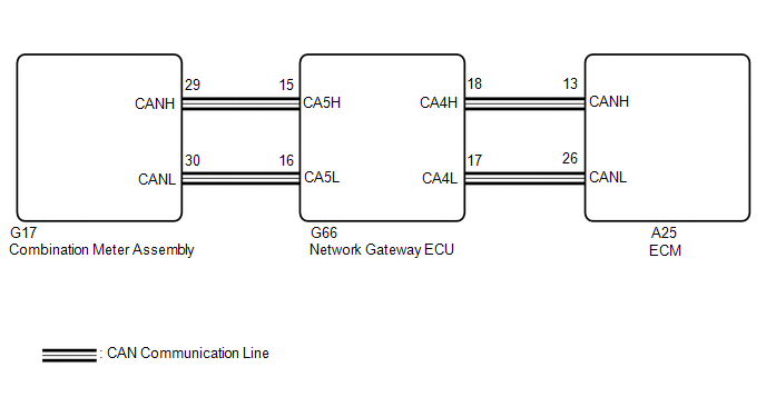
WIRING DIAGRAM
PROCEDURE
| 1. | CHECK THAT MIL IS ILLUMINATED |
(a) Perform troubleshooting in accordance with the table below.
| MIL | Condition | Proceed to |
|---|---|---|
| Illuminates → Turns off | Engine switch on (IG) → engine is started | A |
| Other than above | - | B |
| A | .gif) | CHECK FOR INTERMITTENT PROBLEMS |
|
.gif)
| 2. | CHECK COMMUNICATION BETWEEN TECHSTREAM AND ECM |
(a) Connect the Techstream to the DLC3.
(b) Turn the engine switch on (IG).
(c) Turn the Techstream on.
(d) Check the communication between the Techstream and ECM.
HINT:
It can be checked using the "Engine" item of the Data List.
| Result | Proceed to |
|---|---|
| Communication is possible | A |
| Communication is not possible | B |
| B | | GO TO VC OUTPUT CIRCUIT |
|
| 3. | CHECK WHETHER DTC OUTPUT RECURS |
(a) Connect the Techstream to the DLC3.
(b) Turn the engine switch on (IG).
(c) Turn the Techstream on.
(d) Enter the following menus: System Select / Health Check.
(e) Check if any DTCs have been detected. Note down any DTCs.
| Result | Proceed to |
|---|---|
| DTCs are not output | A |
| Any DTCs is output | B |
HINT:
Check for detected DTCs output from other ECUs which relate to the MIL.
| B | | REPAIR CIRCUIT INDICATED BY OUTPUT |
|
| 4. | PERFORM ACTIVE TEST USING TECHSTREAM |
(a) Connect the Techstream to the DLC3.
(b) Turn the engine switch on (IG).
(c) Turn the Techstream on.
(d) Enter the following menus: Body Electrical / Combination Meter / Active Test / Check Engine Warning.
Body Electrical > Combination Meter > Active Test| Tester Display |
|---|
| Check Engine Warning |
(e) Check the status of the MIL while performing the Active Test.
| Result | Proceed to |
|---|---|
| Changes | A |
| Does not change | B |
| A | | REPLACE ECM |
.gif)
| B | | REPLACE COMBINATION METER ASSEMBLY |
READ NEXT:
 Drive Start Control
DESCRIPTION The drive start control is controlled by the ECM. If the ECM determines that the shift lever and accelerator pedal are operated abnormally, engine output is restricted and, when necessary,
Rough Idling
DESCRIPTION Problem Symptom Suspected Area Trouble Area
Engine speed fluctuation due to abnormal combustion
Idle speed too low or high
Strong engine vibration due to above symptoms
Engine Difficult to Start
DESCRIPTION Problem Symptom Suspected Area Trouble Area
Engine speed fluctuation due to abnormal combustion
Idle speed too low or high
Strong engine vibration due to above symptoms
SEE MORE:
Data List / Active Test
DATA LIST / ACTIVE TEST ACTIVE TEST HINT: Using the Techstream to perform Active Tests allows relays, VSVs, actuators and other items to be operated without removing any parts. This non-intrusive functional inspection can be very useful because intermittent operation may be discovered before parts o
System Voltage Circuit Short to Ground or Open (P056014)
DESCRIPTION The battery supplies electricity to the ECM even when the engine switch is off. This power allows the ECM to store data such as DTC history and freeze frame data. If the battery voltage falls below a minimum level, the stored ECM data will be cleared and the ECM will determine that there
