Lexus ES: Lost Communication with Hybrid/EV Battery Energy Control Module "A" Missing Message (U011187)
DESCRIPTION
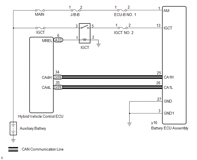
The hybrid vehicle control ECU transmits and receives signals via CAN communication to and from the battery ECU assembly.
| DTC No. | Detection Item | DTC Detection Condition | Trouble Area | MIL | Warning Indicate |
|---|---|---|---|---|---|
| U011187 | Lost Communication with Hybrid/EV Battery Energy Control Module "A" Missing Message | The hybrid vehicle control ECU cannot receive signals from the battery ECU assembly (1 trip detection logic) |
| Comes on | Master Warning Light: Comes on |
MONITOR DESCRIPTION
If the hybrid vehicle control ECU detects a problem with CAN communication with the ECU, it will illuminate the MIL and store a DTC.
MONITOR STRATEGY
| Related DTCs | U0111 (INF U011187): Lost communication with BECM (Battery bus) verify communication |
| Required sensors/components | Main: Battery ECU assembly Sub: Hybrid vehicle control ECU |
| Frequency of operation | Continuous |
| Duration | TMC's intellectual property |
| MIL operation | Immediately |
| Sequence of operation | None |
TYPICAL ENABLING CONDITIONS
| The monitor will run whenever the following DTCs are not stored | TMC's intellectual property |
| Other conditions belong to TMC's intellectual property | - |
TYPICAL MALFUNCTION THRESHOLDS
| TMC's intellectual property | - |
COMPONENT OPERATING RANGE
| Hybrid vehicle control ECU | DTC U0111 (INF U011187) is not detected |
CONFIRMATION DRIVING PATTERN
HINT:
-
After repair has been completed, clear the DTC and then check that the vehicle has returned to normal by performing the following All Readiness check procedure.
Click here
.gif)
-
When clearing the permanent DTCs, refer to the "CLEAR PERMANENT DTC" procedure.
Click here
- Connect the Techstream to the DLC3.
- Turn the power switch on (IG) and turn the Techstream on.
- Clear the DTCs (even if no DTCs are stored, perform the clear DTC procedure).
- Turn the power switch off and wait for 2 minutes or more.
- Turn the power switch on (IG) and turn the Techstream on.
-
Turn the power switch on (READY) and wait for 2 minutes or more. [*1]
HINT:
[*1] : Normal judgment procedure.
The normal judgment procedure is used to complete DTC judgment and also used when clearing permanent DTCs.
- Enter the following menus: Powertrain / Hybrid Control / Utility / All Readiness.
-
Check the DTC judgment result.
HINT:
- If the judgment result shows NORMAL, the system is normal.
- If the judgment result shows ABNORMAL, the system has a malfunction.
- If the judgment result shows INCOMPLETE or N/A, perform the normal judgment procedure again.
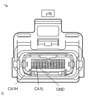
WIRING DIAGRAM
CAUTION / NOTICE / HINT
CAUTION:
-
Before the following operations are conducted, take precautions to prevent electric shock by turning the power switch off, wearing insulated gloves, and removing the service plug grip from HV battery.
.png)
- Inspecting the high-voltage system
- Disconnecting the low voltage connector of the inverter with converter assembly
- Disconnecting the low voltage connector of the HV battery
-
To prevent electric shock, make sure to remove the service plug grip to cut off the high voltage circuit before servicing the vehicle.

-
After removing the service plug grip from the HV battery, put it in your pocket to prevent other technicians from accidentally reconnecting it while you are working on the high-voltage system.

-
After removing the service plug grip, wait for at least 10 minutes before touching any of the high-voltage connectors or terminals. After waiting for 10 minutes, check the voltage at the terminals in the inspection point in the inverter with converter assembly. The voltage should be 0 V before beginning work.
Click here
HINT:
Waiting for at least 10 minutes is required to discharge the high-voltage capacitor inside the inverter with converter assembly.

*a
Without waiting for 10 minutes
NOTICE:
-
After turning the power switch off, waiting time may be required before disconnecting the cable from the negative (-) auxiliary battery terminal. Therefore, make sure to read the disconnecting the cable from the negative (-) auxiliary battery terminal notices before proceeding with work.
Click here
- After removing the service plug grip, do not turn the power switch on (READY), unless instructed by the repair manual because this may cause a malfunction.
- As interlock circuit DTCs or other DTCs may be stored when the power switch is turned on (IG) in the following procedure, make sure to clear the DTCs after inspection.
PROCEDURE
| 1. | CHECK DTC OUTPUT (HV BATTERY) |
(a) Connect the Techstream to the DLC3.
(b) Turn the power switch on (IG).
(c) Enter the following menus: Powertrain / HV Battery / Trouble Codes.
(d) Check and record any hybrid control system DTCs and freeze frame data. Check for DTCs.
Powertrain > HV Battery > Trouble Codes| Result | Proceed to |
|---|---|
| DTCs related to Hybrid Battery System are not output. | A |
| DTCs related to Hybrid Battery System are output. | B |
(e) Turn the power switch off.
| B | .gif) | GO TO DTC CHART (HYBRID BATTERY SYSTEM) |
|
.gif)
| 2. | CHECK BATTERY ECU ASSEMBLY (IGCT VOLTAGE) |
CAUTION:
Be sure to wear insulated gloves.
(a) Check that the service plug grip is not installed.
NOTICE:
After removing the service plug grip, do not turn the power switch on (READY), unless instructed by the repair manual because this may cause a malfunction.
(b) Remove the No. 1 HV battery hose.
Click here
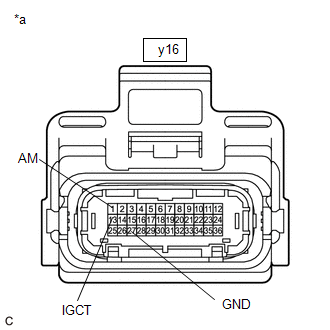
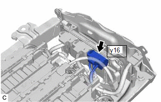
(c) Disconnect the y16 battery ECU assembly connector.
NOTICE:
Before disconnecting the connector, check that it is not loose or disconnected.
(d) Connect the cable to the negative (-) auxiliary battery terminal.
| (e) Measure the voltage according to the value(s) in the table below. Standard Voltage:
NOTICE:
HINT: As there might be an intermittent malfunction in the battery ECU assembly power source circuit, inspect the following even if the measured voltage is as specified:
|
|
(f) Turn the power switch off.
(g) Disconnect the cable from the negative (-) auxiliary battery terminal.
(h) Reconnect the y16 battery ECU assembly connector.
(i) Install the No. 1 HV battery hose.
| NG | | REPAIR OR REPLACE HARNESS OR CONNECTOR (BATTERY ECU ASSEMBLY POWER SOURCE CIRCUIT) |
|
| 3. | CHECK HARNESS AND CONNECTOR (HYBRID VEHICLE CONTROL ECU - BATTERY ECU ASSEMBLY) |
CAUTION:
Be sure to wear insulated gloves.
(a) Check that the service plug grip is not installed.
NOTICE:
After removing the service plug grip, do not turn the power switch on (READY), unless instructed by the repair manual because this may cause a malfunction.
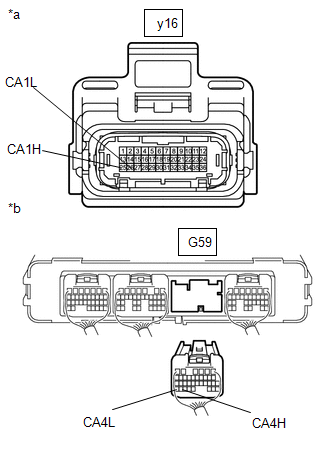
(b) Disconnect the G59 hybrid vehicle control ECU connector.
NOTICE:
- Before disconnecting the connector, check that it is not loose or disconnected.
- Check that each connector between the hybrid vehicle control ECU and battery ECU assembly is not loose or disconnected.
(c) Remove the No. 1 HV battery hose.
Click here
| (d) Disconnect the y16 battery ECU assembly connector. NOTICE:
|
|
| (e) Measure the resistance according to the value(s) in the table below. Standard Resistance:
NOTICE: Make sure that each connector between the battery ECU assembly and hybrid vehicle control ECU is not loose or disconnected and its terminals are not deformed or corroded. |
|
(f) Connect the cable to the negative (-) auxiliary battery terminal.
(g) Turn the power switch on (IG).
(h) Measure the voltage according to the value(s) in the table below.
Standard Voltage:
| Tester Connection | Condition | Specified Condition |
|---|---|---|
| y16-25 (CA1H) - Body ground | Power switch on (IG) | Below 1 V |
| y16-26 (CA1L) - Body ground | Power switch on (IG) | Below 1 V |
NOTICE:
- Turning the power switch on (IG) with the service plug grip removed causes other DTCs to be stored. Clear the DTCs after performing this inspection.
- If the power switch is turned on (IG) with the connectors disconnected, other DTCs will be stored. Be sure to clear the DTCs after the inspection.
(i) Turn the power switch off.
(j) Disconnect the cable from the negative (-) auxiliary battery terminal.
(k) Reconnect the y16 battery ECU assembly connector.
(l) Install the No. 1 HV battery hose.
(m) Reconnect the G59 hybrid vehicle control ECU connector.
| NG | | REPAIR OR REPLACE HARNESS OR CONNECTOR |
|
| 4. | CHECK HYBRID VEHICLE CONTROL ECU |
CAUTION:
Be sure to wear insulated gloves.
(a) Check that the service plug grip is not installed.
NOTICE:
After removing the service plug grip, do not turn the power switch on (READY), unless instructed by the repair manual because this may cause a malfunction.
(b) Remove the No. 1 HV battery hose.
Click here
| (c) Disconnect the y16 battery ECU assembly connector. NOTICE: Before disconnecting the connector, check that it is not loose or disconnected. |
|
(d) Connect the cable to the negative (-) auxiliary battery terminal.
(e) Turn the power switch on (IG).
| (f) Measure the voltage according to the value(s) in the table below. Standard Voltage:
NOTICE:
|
|
(g) Turn the power switch off.
(h) Disconnect the cable from the negative (-) auxiliary battery terminal.
(i) Measure the resistance according to the value(s) in the table below.
Standard Resistance:
| Tester Connection | Condition | Specified Condition |
|---|---|---|
| y16-25 (CA1H) - y16-26 (CA1L) | Power switch off | 108 to 132 Ω |
(j) Reconnect the y16 battery ECU assembly connector.
(k) Install the No. 1 HV battery protector.
| OK | | REPLACE BATTERY ECU ASSEMBLY |
| NG | | REPLACE HYBRID VEHICLE CONTROL ECU |
READ NEXT:
 HVAC Control Module to Hybrid Powertrain Control Module Invalid Serial Data Received (U042481)
DESCRIPTION If the hybrid vehicle control ECU receives an invalid compressor control request from the air conditioning amplifier assembly via CAN communication, it will store this DTC. DTC No. De
Brake Override System
DESCRIPTION When the vehicle is being driven with the accelerator pedal depressed, depressing the brake pedal without releasing the accelerator pedal will activate the brake override system to restric
Transmission Control Switch Circuit
DESCRIPTION When the shift lever is in S, different ranges can be chosen using the floor shift sequential gate. WIRING DIAGRAM Refer to the wiring diagram for the shift paddle switch circuit. Click he
SEE MORE:
Installation
INSTALLATION PROCEDURE 1. INSTALL CAMSHAFT TIMING OIL CONTROL SOLENOID ASSEMBLY (for Intake Side of Bank 2) (a) Apply engine oil to a new O-ring and install it to the camshaft timing oil control solenoid assembly as shown in the illustration. NOTICE: Do not damage the O-ring. *1 O-
Dtc Check / Clear
DTC CHECK / CLEAR CHECK DTC (a) Connect the Techstream to the DLC3. (b) Turn the engine switch on (IG). (c) Turn the Techstream on. (d) Enter the following menus: Body Electrical / Mirror L or Mirror R / Trouble Codes. Body Electrical > Mirror L > Trouble Codes Body Electrical > Mirror R &g
