Lexus ES: Transmission Control Switch Circuit
DESCRIPTION
When the shift lever is in S, different ranges can be chosen using the floor shift sequential gate.
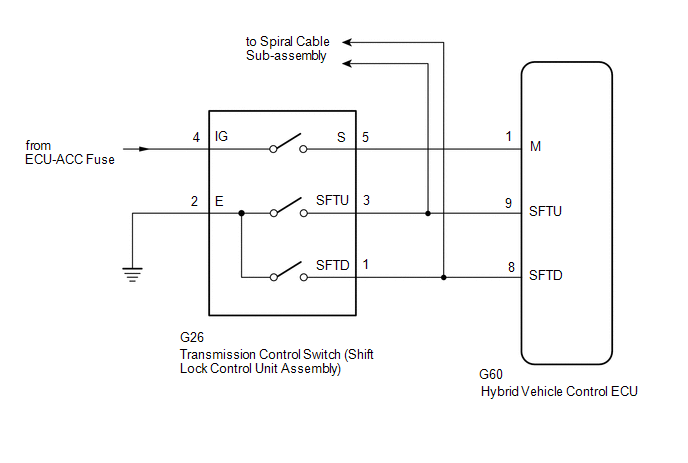
WIRING DIAGRAM
Refer to the wiring diagram for the shift paddle switch circuit.
Click here .gif)
PROCEDURE
| 1. | READ VALUE USING TECHSTREAM (SPORTS SHIFT POSITION) |
(a) Connect the Techstream to the DLC3.
(b) Turn the power switch on (IG).
(c) Enter the following menus: Powertrain / Hybrid Control / Data List / Sports Shift Position.
Powertrain > Hybrid Control > Data List| Tester Display |
|---|
| Sports Shift Position |
(d) Read the value displayed on the Techstream.
| Result | Proceed to |
|---|---|
| The Techstream display changes according to the shift lever operation | A |
| The Techstream display does not change according to the shift lever operation | B |
(e) Turn the power switch off.
| B | .gif) | GO TO STEP 4 |
|
.gif)
| 2. | READ VALUE USING TECHSTREAM (SPORTS SHIFT UP SIGNAL, SPORTS SHIFT DOWN SIGNAL) |
(a) Connect the Techstream to the DLC3.
(b) Turn the power switch on (IG).
(c) Enter the following menus: Powertrain / Hybrid Control / Data List / Sports Shift UP Signal, Sports Shift DOWN Signal.
Powertrain > Hybrid Control > Data List| Tester Display |
|---|
| Sports Shift UP Signal |
| Sports Shift DOWN Signal |
(d) Read the value displayed on the Techstream.
| Result | Proceed to |
|---|---|
| The Techstream display changes according to the transmission control switch (shift lock control unit assembly) operation | A |
| The Techstream display does not change according to the transmission control switch (shift lock control unit assembly) operation | B |
(e) Turn the power switch off.
| B | | GO TO STEP 7 |
|
| 3. | CHECK FOR INTERMITTENT PROBLEMS |
Click here
| OK | | REPLACE HYBRID VEHICLE CONTROL ECU |
| NG | | REPAIR OR REPLACE MALFUNCTIONING PARTS, COMPONENT AND AREA |
| 4. | CHECK HARNESS AND CONNECTOR (POWER SOURCE CIRCUIT) |
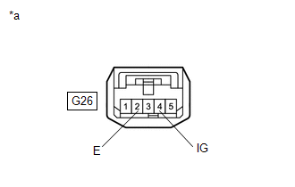
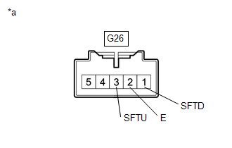
(a) Disconnect the G26 transmission control switch (shift lock control unit assembly) connector.
(b) Turn the power switch on (IG).
| (c) Measure the voltage according to the value(s) in the table below. Standard Voltage:
|
|
(d) Turn the power switch off.
(e) Measure the voltage according to the value(s) in the table below.
Standard Voltage:
| Tester Connection | Condition | Specified Condition |
|---|---|---|
| G26-4 (IG) - Body ground | Power switch off | Below 1 V |
(f) Measure the resistance according to the value(s) in the table below.
Standard Resistance:
| Tester Connection | Condition | Specified Condition |
|---|---|---|
| G26-2 (E) - Body ground | Power switch off | Below 1 Ω |
(g) Reconnect the G26 transmission control switch (shift lock control unit assembly) connector.
| NG | | CHECK POWER SOURCE CIRCUIT |
|
| 5. | INSPECT TRANSMISSION CONTROL SWITCH (SHIFT LOCK CONTROL UNIT ASSEMBLY) |
(a) Inspect the transmission control switch (shift lock control unit assembly).
Click here
| NG | | REPLACE SHIFT LOCK CONTROL UNIT ASSEMBLY |
|
| 6. | CHECK HARNESS AND CONNECTOR (HYBRID VEHICLE CONTROL ECU - TRANSMISSION CONTROL SWITCH (SHIFT LOCK CONTROL UNIT ASSEMBLY)) |
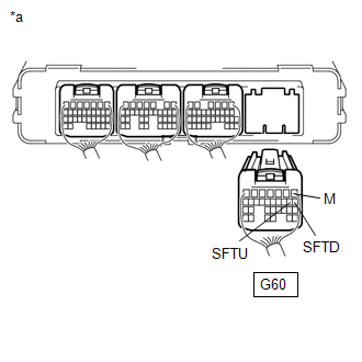
| (a) Disconnect the G60 hybrid vehicle control ECU connector. |
|
(b) Disconnect the G20 spiral cable sub-assembly connector.
(c) Turn the power switch on (IG).
(d) Measure the voltage according to the value(s) in the table below when the shift lever is moved to each position.
Standard Voltage:
| Tester Connection | Condition | Specified Condition |
|---|---|---|
| G60-1 (M) - Body ground | Power switch on (IG) Shift lever in S, "+" or "-" | 11 to 14 V |
| Power switch on (IG) Except shift lever in S, "+" and "-" | Below 1 V |
NOTICE:
If the power switch is turned on (IG) with the hybrid vehicle control ECU connector disconnected, other DTCs will be stored. After performing the inspection, clear the DTCs.
(e) Turn the power switch off.
(f) Measure the resistance according to the value(s) in the table below when the shift lever is moved to each position.
Standard Resistance:
| Tester Connection | Condition | Specified Condition |
|---|---|---|
| G60-9 (SFTU) - Body ground | Shift lever held in "+" | Below 13 Ω |
| G60-9 (SFTU) - Body ground | Shift lever in S | 10 kΩ or higher |
| G60-8 (SFTD) - Body ground | Shift lever held in "-" | Below 13 Ω |
| G60-8 (SFTD) - Body ground | Shift lever in S | 10 kΩ or higher |
(g) Reconnect the G20 spiral cable sub-assembly connector.
(h) Reconnect the G60 hybrid vehicle control ECU connector.
| OK | | REPLACE HYBRID VEHICLE CONTROL ECU |
| NG | | REPAIR OR REPLACE HARNESS OR CONNECTOR |
| 7. | INSPECT TRANSMISSION CONTROL SWITCH (SHIFT LOCK CONTROL UNIT ASSEMBLY) |
(a) Disconnect the G26 transmission control switch (shift lock control unit assembly) connector.
| (b) Measure the resistance according to the value(s) in the table below when the shift lever is moved to each position. Standard Resistance:
|
|
(c) Reconnect the G26 transmission control switch (shift lock control unit assembly) connector.
| NG | | REPLACE SHIFT LOCK CONTROL UNIT ASSEMBLY |
|
| 8. | CHECK HARNESS AND CONNECTOR (TRANSMISSION CONTROL SWITCH (SHIFT LOCK CONTROL UNIT ASSEMBLY) - HYBRID VEHICLE CONTROL ECU) |
(a) Disconnect the G60 hybrid vehicle control ECU connector.
(b) Disconnect the G20 spiral cable sub-assembly connector.
| (c) Measure the resistance according to the value(s) in the table below when the shift lever is moved to each position. Standard Resistance:
|
|
.png)
(d) Reconnect the G20 spiral cable sub-assembly connector.
(e) Reconnect the G60 hybrid vehicle control ECU connector.
| OK | | REPLACE HYBRID VEHICLE CONTROL ECU |
| NG | | REPAIR OR REPLACE HARNESS OR CONNECTOR |
READ NEXT:
 Shift Paddle Switch Circuit
DESCRIPTION Moving the shift lever to S enables the shift range to be selected. The shift range can be selected by operating the "+" or "-" shift paddle switch. WIRING DIAGRAM CAUTION / NOTICE / HINT
Pattern Select Switch EV Mode Circuit
DESCRIPTION The EV drive mode signal will be sent to the hybrid vehicle control ECU when the EV drive mode switch (NO. 3 combination switch assembly) is operated. If the specified conditions are met,
Pattern Select Switch Sport Mode Circuit
DESCRIPTION When selecting sport mode, the switch operation signal is sent to the hybrid vehicle control ECU. Following this, the system enters sport mode and the vehicle will be driven using sport mo
SEE MORE:
Tilt and Telescopic ECU Communication Stop Mode
DESCRIPTION Detection Item Symptom Trouble Area Tilt and Telescopic ECU Communication Stop Mode Any of the following conditions are met:
Communication stop for "Multiplex Tilt and Telescopic" is indicated on the "Communication Bus Check" screen of the Techstream.
Click here
Com
Vehicle Control History
VEHICLE CONTROL HISTORY CHECK VEHICLE CONTROL HISTORY (HYBRID CONTROL SYSTEM) (a) Connect the Techstream to the DLC3. (b) Turn the power switch on (IG). (c) Turn the Techstream on. (d) Enter the following menus: Powertrain / Hybrid Control / Utility / Vehicle Control History (RoB). Powertrain > H
