Lexus ES: Lost Communication with Cruise Control Module Missing Message (U010487)
DESCRIPTION
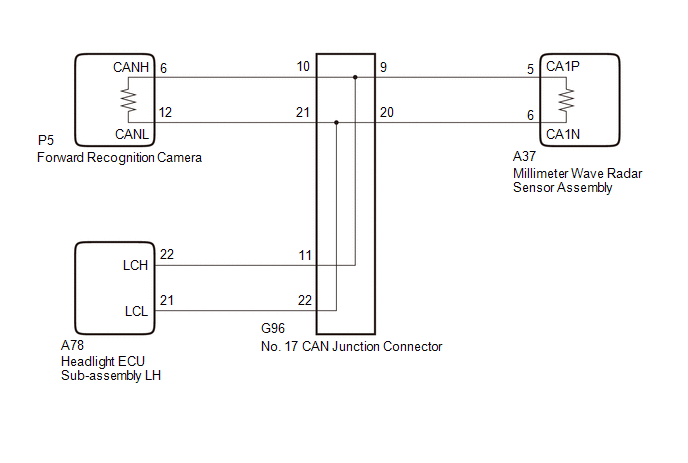
The millimeter wave radar sensor assembly communicates with the forward recognition camera via CAN communication.
If a communication error is detected between the forward recognition camera and millimeter wave radar sensor assembly, the millimeter wave radar sensor assembly stores this DTC.
| DTC No. | Detection Item | DTC Detection Condition | Trouble Area | DTC Output from |
|---|---|---|---|---|
| U010487 | Lost Communication with Cruise Control Module Missing Message |
|
| Front Radar Sensor |
| Pattern | DTC output part name (Display on Techstream) | Suspected Area (Malfunction Status) | |
|---|---|---|---|
| Millimeter Wave Radar Sensor Assembly (Front Radar Sensor) | Forward Recognition Camera (Pre-Collision System) | ||
| U010487 | U023587 | ||
|
○: DTC is output.
-: DTC is not output | |||
| Pattern 1 | ○ | ○ |
|
| Pattern 2 | ○ | - |
|
HINT:
If the DTCs are output simultaneously, the inspection area can be narrowed down.
WIRING DIAGRAM
CAUTION / NOTICE / HINT
NOTICE:
-
After turning the power switch off, waiting time may be required before disconnecting the cable from the negative (-) auxiliary battery terminal. Therefore, make sure to read the disconnecting the cable from the negative (-) auxiliary battery terminal notices before proceeding with work.
Click here
.gif)
- When replacing the millimeter wave radar sensor assembly, always replace it with a new one. If a millimeter wave radar sensor assembly which was installed to another vehicle is used, the information stored in the millimeter wave radar sensor assembly will not match the information from the vehicle and a DTC may be stored.
-
When the millimeter wave radar sensor assembly is replaced with a new one, adjustment of the millimeter wave radar sensor beam axis must be performed.
Click here
- When replacing the forward recognition camera, always replace it with a new one. If a forward recognition camera which was installed to another vehicle is used, the information stored in the forward recognition camera will not match the information from the vehicle and a DTC may be stored.
-
If the forward recognition camera has been replaced with a new one, forward recognition camera adjustment must be performed.
HINT:
Forward recognition camera adjustment can be performed by using either One Time Recognition or Sequential Recognition.
One Time Recognition: Click here
Sequential Recognition: Click here
-
If the headlight ECU sub-assembly LH has been replaced, it is necessary to synchronize the vehicle information and initialize the headlight ECU sub-assembly LH.
Click here
PROCEDURE
| 1. | CHECK FOR DTCs |
(a) Check for pre-collision system DTCs.
Body Electrical > Pre-Collision System > Trouble Codes| Result | Proceed to |
|---|---|
| DTC U023587 is output | A |
| DTC U023587 is not output | B |
| B | .gif) | GO TO STEP 6 |
|
.gif)
| 2. | INSPECT HEADLAMP ECU SUB-ASSEMBLY LH |
(a) Disconnect the A78 headlight ECU sub-assembly LH connector.
(b) Clear the DTCs.
Body Electrical > Front Radar Sensor > Clear DTCs(c) Make sure that the DTC detection conditions are met.
HINT:
If the detection conditions are not met, the system cannot detect the malfunction.
(d) Check for DTCs.
Body Electrical > Front Radar Sensor > Trouble Codes(e) Connect the A78 headlight ECU sub-assembly LH connector.
| Result | Proceed to |
|---|---|
| DTC U010487 is not output | A |
| DTC U010487 is output | B |
| A | | REPLACE HEADLAMP ECU SUB-ASSEMBLY LH |
|
| 3. | CHECK CAN BUS LINES (NO. 17 CAN JUNCTION CONNECTOR) |
(a) Disconnect the cable from the negative (-) auxiliary battery terminal.
(b) Disconnect the G96 No. 17 CAN junction connector.
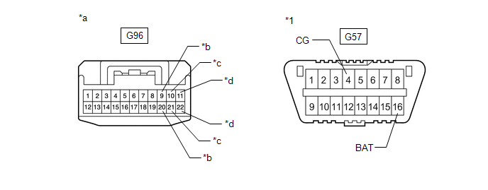
| *1 | DLC3 | - | - |
| *a | Front view of wire harness connector (to No. 17 CAN Junction Connector) | *b | to Millimeter Wave Radar Sensor Assembly |
| *c | to Forward Recognition Camera | *d | to Headlight ECU Sub-assembly LH |
(c) Measure the resistance according to the value(s) in the table below.
Standard Resistance:
| Tester Connection | Condition | Specified Condition | Connected to |
|---|---|---|---|
| G96-10 - G96-21 | Cable disconnected from negative (-) auxiliary battery terminal | 108 to 132 Ω | Forward Recognition Camera |
| G96-9 - G96-20 | Cable disconnected from negative (-) auxiliary battery terminal | 108 to 132 Ω | Millimeter Wave Radar Sensor Assembly |
| G96-11 - G96-22 | Cable disconnected from negative (-) auxiliary battery terminal | 200 Ω or higher | Headlight ECU Sub-assembly LH |
(d) Measure the resistance according to the value(s) in the table below.
Standard Resistance:
| Tester Connection | Condition | Specified Condition | Connected to |
|---|---|---|---|
| G96-10 - G57-4(CG) | Cable disconnected from negative (-) auxiliary battery terminal | 200 Ω or higher | Forward Recognition Camera |
| G96-21 - G57-4(CG) | Cable disconnected from negative (-) auxiliary battery terminal | 200 Ω or higher | |
| G96-10 - G57-16(BAT) | Cable disconnected from negative (-) auxiliary battery terminal | 6 kΩ or higher | |
| G96-21 - G57-16(BAT) | Cable disconnected from negative (-) auxiliary battery terminal | 6 kΩ or higher | |
| G96-9 - G57-4(CG) | Cable disconnected from negative (-) auxiliary battery terminal | 200 Ω or higher | Millimeter Wave Radar Sensor Assembly |
| G96-20 - G57-4(CG) | Cable disconnected from negative (-) auxiliary battery terminal | 200 Ω or higher | |
| G96-9 - G57-16(BAT) | Cable disconnected from negative (-) auxiliary battery terminal | 6 kΩ or higher | |
| G96-20 - G57-16(BAT) | Cable disconnected from negative (-) auxiliary battery terminal | 6 kΩ or higher | |
| G96-11 - G57-4(CG) | Cable disconnected from negative (-) auxiliary battery terminal | 200 Ω or higher | Headlight ECU Sub-assembly LH |
| G96-22 - G57-4(CG) | Cable disconnected from negative (-) auxiliary battery terminal | 200 Ω or higher | |
| G96-11 - G57-16(BAT) | Cable disconnected from negative (-) auxiliary battery terminal | 6 kΩ or higher | |
| G96-22 - G57-16(BAT) | Cable disconnected from negative (-) auxiliary battery terminal | 6 kΩ or higher |
(e) Connect the G96 No. 17 CAN junction connector.
| Result | Proceed to |
|---|---|
| OK | A |
| NG (Connected to: Forward Recognition Camera) | B |
| NG (Connected to: Millimeter Wave Radar Sensor Assembly) | C |
| NG (Connected to: Headlight ECU Sub-assembly LH) | D |
| A | | REPLACE NO. 17 CAN JUNCTION CONNECTOR |
| C | | GO TO STEP 5 |
| D | | REPAIR OR REPLACE CAN BUS MAIN LINE OR CONNECTOR (HEADLIGHT ECU SUB-ASSEMBLY LH - NO. 17 CAN JUNCTION CONNECTOR) |
|
| 4. | CHECK CAN BUS LINES (FORWARD RECOGNITION CAMERA - NO. 17 CAN JUNCTION CONNECTOR) |
(a) Disconnect the P5 forward recognition camera connector.
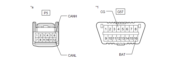
| *1 | DLC3 | - | - |
| *a | Front view of wire harness connector (to Forward Recognition Camera) | - | - |
(b) Measure the resistance according to the value(s) in the table below.
Standard Resistance:
| Tester Connection | Condition | Specified Condition |
|---|---|---|
| P5-6 (CANH) - P5-12 (CANL) | Cable disconnected from negative (-) auxiliary battery terminal | 108 to 132Ω |
(c) Measure the resistance according to the value(s) in the table below.
Standard Resistance:
| Tester Connection | Condition | Specified Condition |
|---|---|---|
| P5-6 (CANH) - G57-4 (CG) | Cable disconnected from negative (-) auxiliary battery terminal | 200 Ω or higher |
| P5-12 (CANL) - G57-4 (CG) | Cable disconnected from negative (-) auxiliary battery terminal | 200 Ω or higher |
| P5-6 (CANH) - G57-16 (BAT) | Cable disconnected from negative (-) auxiliary battery terminal | 6 kΩ or higher |
| P5-12 (CANL) - G57-16 (BAT) | Cable disconnected from negative (-) auxiliary battery terminal | 6 kΩ or higher |
(d) Connect the P5 forward recognition camera connector.
| OK | | REPLACE FORWARD RECOGNITION CAMERA |
| NG | | REPAIR OR REPLACE CAN BUS MAIN LINE OR CONNECTOR (FORWARD RECOGNITION CAMERA - NO. 17 CAN JUNCTION CONNECTOR) |
| 5. | CHECK CAN BUS LINES (MILLIMETER WAVE RADAR SENSOR ASSEMBLY - NO. 17 CAN JUNCTION CONNECTOR) |
(a) Disconnect the A37 millimeter wave radar sensor assembly connector.
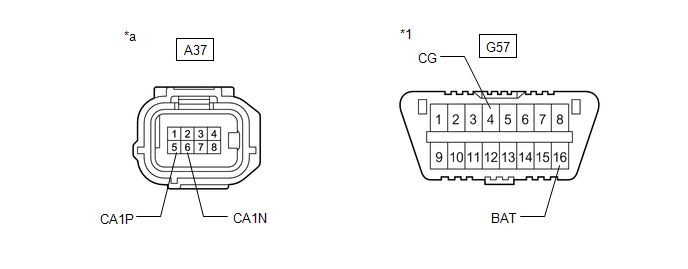
| *1 | DLC3 | - | - |
| *a | Front view of wire harness connector (to Millimeter Wave Radar Sensor Assembly) | - | - |
(b) Measure the resistance according to the value(s) in the table below.
Standard Resistance:
| Tester Connection | Condition | Specified Condition |
|---|---|---|
| A37-5 (CA1P) - A37-6 (CA1N) | Cable disconnected from negative (-) auxiliary battery terminal | 108 to 132Ω |
(c) Measure the resistance according to the value(s) in the table below.
Standard Resistance:
| Tester Connection | Condition | Specified Condition |
|---|---|---|
| A37-5 (CA1P) - G57-4 (CG) | Cable disconnected from negative (-) auxiliary battery terminal | 200 Ω or higher |
| A37-6 (CA1N) - G57-4 (CG) | Cable disconnected from negative (-) auxiliary battery terminal | 200 Ω or higher |
| A37-5 (CA1P) - G57-16 (BAT) | Cable disconnected from negative (-) auxiliary battery terminal | 6 kΩ or higher |
| A37-6 (CA1N) - G57-16 (BAT) | Cable disconnected from negative (-) auxiliary battery terminal | 6 kΩ or higher |
(d) Connect the A37 millimeter wave radar sensor assembly connector.
| OK | | REPLACE MILLIMETER WAVE RADAR SENSOR ASSEMBLY |
| NG | | REPAIR OR REPLACE CAN BUS MAIN LINE OR CONNECTOR (MILLIMETER WAVE RADAR SENSOR ASSEMBLY - NO. 17 CAN JUNCTION CONNECTOR) |
| 6. | CHECK CONNECTOR (FORWARD RECOGNITION CAMERA) |
(a) Check the locking part and terminals of the forward recognition camera connector.
NOTICE:
- Make sure the connector is not loose or disconnected.
- Make sure that the connector and terminals are not deformed or corroded.
OK:
The connector and terminals are normal.
| NG | | REPAIR OR REPLACE HARNESS OR CONNECTOR (FORWARD RECOGNITION CAMERA) |
|
| 7. | CHECK HARNESS AND CONNECTOR (FORWARD RECOGNITION CAMERA POWER SOURCE CIRCUIT) |
(a) Disconnect the cable from the negative (-) auxiliary battery terminal.
| (b) Disconnect the P5 forward recognition camera connector. |
|
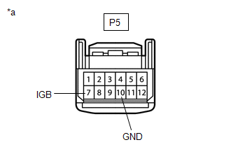
(c) Measure the resistance according to the value(s) in the table below.
Standard Resistance:
| Tester Connection | Condition | Specified Condition |
|---|---|---|
| P5-10 (GND) - Body ground | Always | Below 1 Ω |
(d) Connect the cable to the negative (-) auxiliary battery terminal.
(e) Measure the voltage according to the value(s) in the table below.
Standard Voltage:
| Tester Connection | Condition | Specified Condition |
|---|---|---|
| P5-7 (IGB) - Body ground | Power switch on (IG) | 11 to 14 V |
(f) Connect the P5 forward recognition camera connector.
| NG | | REPAIR OR REPLACE HARNESS OR CONNECTOR (FORWARD RECOGNITION CAMERA POWER SOURCE CIRCUIT) |
|
| 8. | INSPECT FORWARD RECOGNITION CAMERA (WAVEFORM) |
(a) Turn the power switch off.
(b) Disconnect the G96 No. 17 CAN junction connector.
(c) Turn the power switch on (IG).
(d) Using an oscilloscope, measure the waveform at G96 No. 17 CAN junction connector.
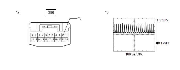
| *a | Front view of wire harness connector (to No. 17 CAN Junction Connector) | *b | Waveform |
| *c | to Forward Recognition Camera | - | - |
Measurement Condition:
| Tester Connection | Condition | Tool Setting |
|---|---|---|
| G96-10 - Body ground | Power switch on (IG) | 1 V/DIV., 100 μs/DIV. |
NOTICE:
The oscilloscope waveform is for reference only and does not include noise, fluctuations, etc.
OK:
A waveform similar to that in the illustration can be observed.
(e) Connect the G96 No. 17 CAN junction connector.
| OK | | REPLACE MILLIMETER WAVE RADAR SENSOR ASSEMBLY |
| NG | | REPLACE FORWARD RECOGNITION CAMERA |
READ NEXT:
 Software Incompatibility with Cruise Control Module Invalid/Incompatible Software Component (U030557)
DESCRIPTION The millimeter wave radar sensor assembly receives vehicle information from the forward recognition camera via CAN communication. If the vehicle information stored in the forward recogniti
Precaution
PRECAUTION PRECAUTION FOR DISCONNECTING CABLE FROM NEGATIVE BATTERY TERMINAL NOTICE:
When disconnecting the cable from the negative (-) battery terminal, initialize the following systems after the
SEE MORE:
Installation
INSTALLATION PROCEDURE 1. INSTALL NO. 1 FUEL TANK PROTECTOR SUB-ASSEMBLY (a) Engage the 2 claws to install the No. 1 fuel tank protector sub-assembly to the fuel tank assembly. 2. INSTALL FUEL TANK MAIN TUBE SUB-ASSEMBLY (a) Engage the 2 clamps to install the fuel tank main tube sub-assembly to the
AUTO Power Retract Mirrors do not operate
DESCRIPTION The outer mirror switch assembly sends the retractable outer mirror switch signal to the main body ECU (multiplex network body ECU). The main body ECU (multiplex network body ECU) sends the auto retract/return signal to the outer mirror control ECU assemblies via CAN communication, which
