Lexus ES: Linear Solenoid Power Supply System Malfunction (C120C)
DESCRIPTION
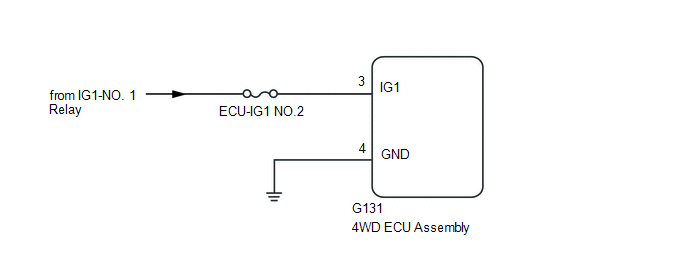
This DTC is output by the 4WD ECU assembly if a malfunction occurs in the linear solenoid power supply system.
| DTC No. | Detection Item | DTC Detection Condition | Trouble Area |
|---|---|---|---|
| C120C | Linear Solenoid Power Supply System Malfunction |
|
|
| Vehicle Condition | ||||
|---|---|---|---|---|
| Pattern 1 | Pattern 2 | Pattern 3 | ||
| Diagnosis Condition | When the 4WD relay is on and the voltage at the IG1 terminal is 9.5 V or more | ○ | - | - |
| When the 4WD relay is on and the voltage at the IG1 terminal is less than 9.5 V | - | ○ | - | |
| While the 4WD relay is off | - | - | ○ | |
| Malfunction Status | The 4WD relay monitor remains off | ○ | ○ | - |
| The 4WD relay monitor remains on immediately after the engine switch is turned on (IG) | - | - | ○ | |
| Detection Time | 1 second or more | 1 second or more | 1 second or more | |
| Number of Trips | 1 trip | 1 trip | 1 trip | |
HINT:
DTC will be output when conditions for any of the patterns in the table above are met.
WIRING DIAGRAM
CAUTION / NOTICE / HINT
NOTICE:
Inspect the fuses for circuits related to this system before performing the following inspection procedure.
PROCEDURE
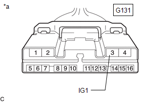
| 1. | CHECK HARNESS AND CONNECTOR (IG1 TERMINAL) |
| (a) Disconnect the G131 4WD ECU assembly connector. |
|
(b) Turn the engine switch on (IG).
(c) Measure the voltage according to the value(s) in the table below.
Standard Voltage:
| Tester Connection | Condition | Specified Condition |
|---|---|---|
| G131-3 (IG1) - Body ground | Engine switch on (IG) | 11 to 14 V |
| NG | .gif) | REPAIR OR REPLACE HARNESS OR CONNECTOR |
|
.gif)
| 2. | CHECK HARNESS AND CONNECTOR (GND TERMINAL) |
(a) Turn the engine switch off.
(b) Measure the resistance according to the value(s) in the table below.
Standard Resistance:
| Tester Connection | Condition | Specified Condition |
|---|---|---|
| G131-4 (GND) - Body ground | Always | Below 1 Ω |
| NG | | REPAIR OR REPLACE HARNESS OR CONNECTOR |
|
| 3. | RECONFIRM DTC |
(a) Clear the DTC.
Chassis > Four Wheel Drive > Clear DTCs(b) Turn the engine switch on (IG).
(c) Check that no DTCs other than DTC C120C have been output.
Chassis > Four Wheel Drive > Trouble Codes| Result | Proceed to |
|---|---|
| DTCs other than DTC C120C are not output | A |
| DTCs other than DTC C120C are output | B |
| A | | REPLACE 4WD ECU ASSEMBLY |
.gif)
| B | | REPAIR CIRCUIT INDICATED BY OUTPUT CODE |
READ NEXT:
 Low or High Power Supply Voltage (C1241)
DESCRIPTION If a malfunction in the power source circuit occurs, or a malfunction in communication with the skid control ECU (brake actuator assembly) or in a speed sensor occurs, the 4WD ECU assembly
Engine Circuit Malfunction (C1280)
DESCRIPTION If a malfunction in the ECM circuit occurs, the 4WD ECU assembly will output this DTC. DTC No. Detection Item DTC Detection Condition Trouble Area C1280 Engine Circuit Malfu
ABS Malfunction (C1296)
DESCRIPTION If a malfunction in the speed sensor signal circuit or yaw rate and acceleration sensor (airbag ECU assembly) circuit occurs, the 4WD ECU assembly will output this DTC. The airbag ECU asse
SEE MORE:
Pressure Control Solenoid "B" Actuator Stuck Off (P07757F)
DESCRIPTION Based on signals from the transmission revolution sensors (NT and NC), the actual gear is detected. The ECM compares the actual gear with the shift schedule in the ECM memory to detect mechanical malfunctions of the solenoid valves, transmission valve body assembly and automatic transaxl
Motor Generator Control ECU Communication Stop Mode
DESCRIPTION Detection Item Symptom Trouble Area Motor Generator Control ECU Communication Stop Mode Any of the following conditions are met:
Communication stop for "Motor Generator" is indicated on the "Communication Bus Check" screen of the Techstream.
Click here
Communication
