Lexus ES: Left Rear Wheel Speed Sensor Circuit Short to Ground or Open (C050C14)
DESCRIPTION
Refer to DTC C050C12
Click here .gif)
| DTC No. | Detection Item | DTC Detection Condition | Trouble Area |
|---|---|---|---|
| C050C14 | Left Rear Wheel Speed Sensor Circuit Short to Ground or Open | A short or open circuit is detected in the speed sensor signal circuit for 0.12 seconds or more. |
|
*1: for 2WD
*2: for AWD
DTC Detection Conditions: C050C14| Vehicle Condition | |||
|---|---|---|---|
| Pattern 1 | Pattern 2 | ||
| Diagnosis Condition | - | - | - |
| Malfunction Status | An open circuit is detected in the speed sensor signal circuit. | ○ | - |
| A short circuit is detected in the speed sensor signal circuit. | - | ○ | |
| Detection Time | 0.12 seconds or more. | 0.12 seconds or more. | |
| Number of Trips | 1 trip | 1 trip | |
HINT:
DTC will be output when conditions for either of the patterns in the table above are met.
WIRING DIAGRAM
Refer to DTC C050C12.
Click here
CAUTION / NOTICE / HINT
NOTICE:
-
After replacing the skid control ECU (brake actuator assembly), perform acceleration sensor zero point calibration and store system information memorization.
Click here
-
After replacing or removing and installing a speed sensor, perform Dealer Mode (Signal Check) inspection to confirm that the speed sensors are operating correctly.
Click here
PROCEDURE
| 1. | CHECK VEHICLE |
(a) Check the vehicle specification.
| Result | Proceed to |
|---|---|
| for 2WD (w/o AVS) | A |
| for 2WD (w/ AVS) | B |
| for AWD | C |
| B |  | GO TO STEP 7 |
| C | | GO TO STEP 12 |
|

| 2. | CHECK HARNESS AND CONNECTOR (SENSOR GROUND CIRCUIT) |
| (a) Make sure that there is no looseness at the locking part and the connecting part of the connectors. OK: The connector is securely connected. |
|
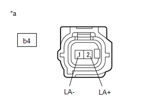
(b) Disconnect the b4 rear speed sensor LH (rear axle hub and bearing assembly LH) connector.
(c) Check both the connector case and the terminals for deformation and corrosion.
OK:
No deformation or corrosion.
(d) Turn the engine switch on (IG).
(e) Measure the voltage according to the value(s) in the table below.
Standard Voltage:
| Tester Connection | Condition | Specified Condition |
|---|---|---|
| b4-2 (LA+) - b4-1 (LA-) | Engine switch on (IG) | 11 to 14 V |
| NG | | GO TO STEP 5 |
|
| 3. | INSPECT NO. 2 PARKING BRAKE WIRE ASSEMBLY |
| (a) Make sure that there is no looseness at the locking part and the connecting part of the connectors. OK: The connector is securely connected. |
|
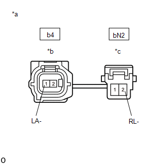
(b) Disconnect the b4 skid control sensor wire LH (No. 2 parking brake wire assembly) connector.
(c) Disconnect the bN2 skid control sensor wire LH (No. 2 parking brake wire assembly) connector.
(d) Check both the connector case and the terminals for deformation and corrosion.
OK:
No deformation or corrosion.
(e) Measure the resistance according to the value(s) in the table below.
Standard Resistance:
| Tester Connection | Condition | Specified Condition |
|---|---|---|
| b4-1 (LA-) or bN2-2 (RL-) - Body ground and other terminals | Always | 10 kΩ or higher |
| NG | | REPLACE NO. 2 PARKING BRAKE WIRE ASSEMBLY |
|
| 4. | CHECK HARNESS AND CONNECTOR (NO. 2 PARKING BRAKE WIRE ASSEMBLY - BRAKE ACTUATOR ASSEMBLY) |
(a) Make sure that there is no looseness at the locking part and the connecting part of the connectors.
OK:
The connector is securely connected.
(b) Disconnect the A40 skid control ECU (brake actuator assembly) connector.
(c) Disconnect the bN2 skid control sensor wire LH (No. 2 parking brake wire assembly) connector.
(d) Check both the connector case and the terminals for deformation and corrosion.
OK:
No deformation or corrosion.
(e) Measure the resistance according to the value(s) in the table below.
Standard Resistance:
| Tester Connection | Condition | Specified Condition |
|---|---|---|
| bN2-2 (RL-) or A40-23 (RL-) - Body ground | Always | 10 kΩ or higher |
| OK | | REPLACE REAR AXLE HUB AND BEARING ASSEMBLY LH |
| NG | | REPAIR OR REPLACE HARNESS OR CONNECTOR |
| 5. | INSPECT NO. 2 PARKING BRAKE WIRE ASSEMBLY |
| (a) Make sure that there is no looseness at the locking part and the connecting part of the connectors. OK: The connector is securely connected. |
|
(b) Disconnect the b4 skid control sensor wire LH (No. 2 parking brake wire assembly) connector.
(c) Disconnect the bN2 skid control sensor wire LH (No. 2 parking brake wire assembly) connector.
(d) Check both the connector case and the terminals for deformation and corrosion.
OK:
No deformation or corrosion.
(e) Measure the resistance according to the value(s) in the table below.
Standard Resistance:
| Tester Connection | Condition | Specified Condition |
|---|---|---|
| b4-1 (LA-) - bN2-2 (RL-) | Always | Below 1 Ω |
| NG | | REPLACE NO. 2 PARKING BRAKE WIRE ASSEMBLY |
|
| 6. | CHECK HARNESS AND CONNECTOR (NO. 2 PARKING BRAKE WIRE ASSEMBLY - BRAKE ACTUATOR ASSEMBLY) |
(a) Make sure that there is no looseness at the locking part and the connecting part of the connectors.
OK:
The connector is securely connected.
(b) Disconnect the A40 skid control ECU (brake actuator assembly) connector.
(c) Disconnect the bN2 skid control sensor wire LH (No. 2 parking brake wire assembly) connector.
(d) Check both the connector case and the terminals for deformation and corrosion.
OK:
No deformation or corrosion.
(e) Measure the resistance according to the value(s) in the table below.
Standard Resistance:
| Tester Connection | Condition | Specified Condition |
|---|---|---|
| bN2-2 (RL-) - A40-23 (RL-) | Always | Below 1 Ω |
| OK | | REPLACE BRAKE ACTUATOR ASSEMBLY |
| NG | | REPAIR OR REPLACE HARNESS OR CONNECTOR |
| 7. | CHECK HARNESS AND CONNECTOR (SENSOR GROUND CIRCUIT) |
| (a) Make sure that there is no looseness at the locking part and the connecting part of the connectors. OK: The connector is securely connected. |
|
(b) Disconnect the b4 rear speed sensor LH (rear axle hub and bearing assembly LH) connector.
(c) Check both the connector case and the terminals for deformation and corrosion.
OK:
No deformation or corrosion.
(d) Turn the engine switch on (IG).
(e) Measure the voltage according to the value(s) in the table below.
Standard Voltage:
| Tester Connection | Condition | Specified Condition |
|---|---|---|
| b4-2 (LA+) - b4-1 (LA-) | Engine switch on (IG) | 11 to 14 V |
| NG | | GO TO STEP 10 |
|
| 8. | INSPECT NO. 2 PARKING BRAKE WIRE ASSEMBLY |
| (a) Make sure that there is no looseness at the locking part and the connecting part of the connectors. OK: The connector is securely connected. |
|
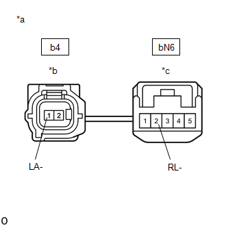
(b) Disconnect the b4 skid control sensor wire LH (No. 2 parking brake wire assembly) connector.
(c) Disconnect the bN6 skid control sensor wire LH (No. 2 parking brake wire assembly) connector.
(d) Check both the connector case and the terminals for deformation and corrosion.
OK:
No deformation or corrosion.
(e) Measure the resistance according to the value(s) in the table below.
Standard Resistance:
| Tester Connection | Condition | Specified Condition |
|---|---|---|
| b4-1 (LA-) or bN6-2 (RL-) - Body ground and other terminals | Always | 10 kΩ or higher |
| NG | | REPLACE NO. 2 PARKING BRAKE WIRE ASSEMBLY |
|
| 9. | CHECK HARNESS AND CONNECTOR (NO. 2 PARKING BRAKE WIRE ASSEMBLY - BRAKE ACTUATOR ASSEMBLY) |
(a) Make sure that there is no looseness at the locking part and the connecting part of the connectors.
OK:
The connector is securely connected.
(b) Disconnect the A40 skid control ECU (brake actuator assembly) connector.
(c) Disconnect the bN6 skid control sensor wire LH (No. 2 parking brake wire assembly) connector.
(d) Check both the connector case and the terminals for deformation and corrosion.
OK:
No deformation or corrosion.
(e) Measure the resistance according to the value(s) in the table below.
Standard Resistance:
| Tester Connection | Condition | Specified Condition |
|---|---|---|
| bN6-2 (RL-) or A40-23 (RL-) - Body ground | Always | 10 kΩ or higher |
| OK | | REPLACE REAR AXLE HUB AND BEARING ASSEMBLY LH |
| NG | | REPAIR OR REPLACE HARNESS OR CONNECTOR |
| 10. | INSPECT NO. 2 PARKING BRAKE WIRE ASSEMBLY |
| (a) Make sure that there is no looseness at the locking part and the connecting part of the connectors. OK: The connector is securely connected. |
|

(b) Disconnect the b4 skid control sensor wire LH (No. 2 parking brake wire assembly) connector.
(c) Disconnect the bN6 skid control sensor wire LH (No. 2 parking brake wire assembly) connector.
(d) Check both the connector case and the terminals for deformation and corrosion.
OK:
No deformation or corrosion.
(e) Measure the resistance according to the value(s) in the table below.
Standard Resistance:
| Tester Connection | Condition | Specified Condition |
|---|---|---|
| b4-1 (LA-) - bN6-2 (RL-) | Always | Below 1 Ω |
| NG | | REPLACE NO. 2 PARKING BRAKE WIRE ASSEMBLY |
|
| 11. | CHECK HARNESS AND CONNECTOR (NO. 2 PARKING BRAKE WIRE ASSEMBLY - BRAKE ACTUATOR ASSEMBLY) |
(a) Make sure that there is no looseness at the locking part and the connecting part of the connectors.
OK:
The connector is securely connected.
(b) Disconnect the A40 skid control ECU (brake actuator assembly) connector.
(c) Disconnect the bN6 skid control sensor wire LH (No. 2 parking brake wire assembly) connector.
(d) Check both the connector case and the terminals for deformation and corrosion.
OK:
No deformation or corrosion.
(e) Measure the resistance according to the value(s) in the table below.
Standard Resistance:
| Tester Connection | Condition | Specified Condition |
|---|---|---|
| bN6-2 (RL-) - A40-23 (RL-) | Always | Below 1 Ω |
| OK | | REPLACE BRAKE ACTUATOR ASSEMBLY |
| NG | | REPAIR OR REPLACE HARNESS OR CONNECTOR |
| 12. | CHECK HARNESS AND CONNECTOR (SENSOR GROUND CIRCUIT) |
| (a) Make sure that there is no looseness at the locking part and the connecting part of the connectors. OK: The connector is securely connected. |
|
(b) Disconnect the b4 rear speed sensor LH connector.
(c) Check both the connector case and the terminals for deformation and corrosion.
OK:
No deformation or corrosion.
(d) Turn the engine switch on (IG).
(e) Measure the voltage according to the value(s) in the table below.
Standard Voltage:
| Tester Connection | Condition | Specified Condition |
|---|---|---|
| b4-2 (LA+) - b4-1 (LA-) | Engine switch on (IG) | 11 to 14 V |
| NG | | GO TO STEP 5 |
|
| 13. | INSPECT NO. 2 PARKING BRAKE WIRE ASSEMBLY |
| (a) Make sure that there is no looseness at the locking part and the connecting part of the connectors. OK: The connector is securely connected. |
|
(b) Disconnect the b4 skid control sensor wire LH (No. 2 parking brake wire assembly) connector.
(c) Disconnect the bN2 skid control sensor wire LH (No. 2 parking brake wire assembly) connector.
(d) Check both the connector case and the terminals for deformation and corrosion.
OK:
No deformation or corrosion.
(e) Measure the resistance according to the value(s) in the table below.
Standard Resistance:
| Tester Connection | Condition | Specified Condition |
|---|---|---|
| b4-1 (LA-) or bN2-2 (RL-) - Body ground and other terminals | Always | 10 kΩ or higher |
| NG | | REPLACE NO. 2 PARKING BRAKE WIRE ASSEMBLY |
|
| 14. | CHECK HARNESS AND CONNECTOR (NO. 2 PARKING BRAKE WIRE ASSEMBLY - BRAKE ACTUATOR ASSEMBLY) |
(a) Make sure that there is no looseness at the locking part and the connecting part of the connectors.
OK:
The connector is securely connected.
(b) Disconnect the A40 skid control ECU (brake actuator assembly) connector.
(c) Disconnect the bN2 skid control sensor wire LH (No. 2 parking brake wire assembly) connector.
(d) Check both the connector case and the terminals for deformation and corrosion.
OK:
No deformation or corrosion.
(e) Measure the resistance according to the value(s) in the table below.
Standard Resistance:
| Tester Connection | Condition | Specified Condition |
|---|---|---|
| bN2-2 (RL-) or A40-23 (RL-) - Body ground | Always | 10 kΩ or higher |
| OK | | REPLACE REAR SPEED SENSOR LH |
| NG | | REPAIR OR REPLACE HARNESS OR CONNECTOR |
READ NEXT:
 Left Rear Wheel Speed Sensor Signal Stuck Low (C050C23)
DESCRIPTION Refer to DTC C050C12 Click here DTC No. Detection Item DTC Detection Condition Trouble Area C050C23 Left Rear Wheel Speed Sensor Signal Stuck Low
When the vehicle is
Left Rear Wheel Speed Sensor Signal Stuck Low (C050C23)
DESCRIPTION Refer to DTC C050C12 Click here DTC No. Detection Item DTC Detection Condition Trouble Area C050C23 Left Rear Wheel Speed Sensor Signal Stuck Low
When the vehicle is
Left Rear Wheel Speed Sensor Signal Stuck High (C050C24)
DESCRIPTION Refer to DTC C050C12 Click here DTC No. Detection Item DTC Detection Condition Trouble Area C050C24 Left Rear Wheel Speed Sensor Signal Stuck High The speed sensor signa
SEE MORE:
On-vehicle Inspection
ON-VEHICLE INSPECTION CAUTION / NOTICE / HINT CAUTION: Do not remove the radiator cap sub-assembly while the engine and radiator assembly are still hot. Pressurized, hot engine coolant and steam may be released and cause serious burns. PROCEDURE 1. CHECK RADIATOR CAP SUB-ASSEMBLY CAUTION: Do not re
Components
COMPONENTS ILLUSTRATION *1 DRIVE MODE SELECT SWITCH (COMBINATION SWITCH ASSEMBLY) *2 INSTRUMENT CLUSTER FINISH PANEL ASSEMBLY
