Lexus ES: Left Electric Parking Brake Actuator Control Circuit Open (C060B13)
DESCRIPTION
| DTC No. | Detection Item | DTC Detection Condition | Trouble Area | Memory | Note |
|---|---|---|---|---|---|
| C060B13 | Left Electric Parking Brake Actuator Control Circuit Open |
|
| DTC stored | An electric parking brake system malfunction is displayed on the multi-information display. |
WIRING DIAGRAM
Click here .gif)
CAUTION / NOTICE / HINT
NOTICE:
- The electric parking brake may still operate up to 20 seconds after the engine switch is turned off. Before disconnecting connectors or fuses, turn the engine switch off and wait 20 seconds or more.
-
After replacing the skid control ECU (brake actuator assembly), perform acceleration sensor zero point calibration and store system information memorization.
Click here
- When replacing the skid control ECU (brake actuator assembly), operate the electric parking brake switch assembly as the parking brake indicator light blinks (red) when the engine switch is first turned on (IG).
PROCEDURE
| 1. | INSPECT NO. 2 PARKING BRAKE WIRE ASSEMBLY |
(a) Turn the engine switch off.
(b) Make sure that there is no looseness at the locking part and the connecting part of the connectors.
OK:
The connector is securely connected.
(c) Disconnect the bN4 and b3 No. 2 parking brake wire assembly connectors.
(d) Check both the connector case and the terminals for deformation and corrosion.
OK:
No deformation or corrosion.
(e) Measure the resistance according to the value(s) in the table below.
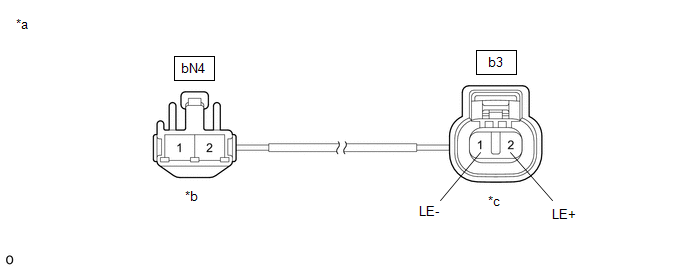
| *a | Front view of No. 2 Parking Brake Wire Assembly | *b | (to wire harness connector) |
| *c | (to Parking Brake Actuator Assembly LH) | - | - |
Standard Resistance:
| Tester Connection | Condition | Specified Condition |
|---|---|---|
| bN4-2 - b3-2 (LE+) | Always | Below 1 Ω |
| bN4-2 - Other terminals | Always | 10 kΩ or higher |
| bN4-1 - b3-1 (LE-) | Always | Below 1 Ω |
| bN4-1 - Other terminals | Always | 10 kΩ or higher |
| NG |  | REPLACE NO. 2 PARKING BRAKE WIRE ASSEMBLY |
|

| 2. | CHECK HARNESS AND CONNECTOR (SKID CONTROL ECU (BRAKE ACTUATOR ASSEMBLY) - PARKING BRAKE ACTUATOR ASSEMBLY LH) |
(a) Turn the engine switch off.
(b) Make sure the No. 2 parking brake wire assembly is securely installed.
(c) Disconnect the A40 skid control ECU (brake actuator assembly) connector.
(d) Disconnect the b3 parking brake actuator assembly LH connector.
(e) Measure the resistance according to the value(s) in the table below.
Standard Resistance:
| Tester Connection | Condition | Specified Condition |
|---|---|---|
| A40-13 (MRL+) - b3-2 (LE+) | Always | Below 1 Ω |
| A40-12 (MRL-) - b3-1 (LE-) | Always | Below 1 Ω |
| NG | | REPAIR OR REPLACE HARNESS OR CONNECTOR |
|
| 3. | INSPECT PARKING BRAKE ACTUATOR ASSEMBLY LH |
(a) Remove the parking brake actuator assembly LH.
Click here
(b) Inspect the parking brake actuator assembly LH.
Click here
| OK | | REPLACE SKID CONTROL ECU (BRAKE ACTUATOR ASSEMBLY) |
| NG | | REPLACE PARKING BRAKE ACTUATOR ASSEMBLY LH |
READ NEXT:
 Left Electric Parking Brake Actuator Signal Stuck In Range (C060E2A)
DESCRIPTION DTC No. Detection Item DTC Detection Condition Trouble Area Memory Note C060E2A Left Electric Parking Brake Actuator Signal Stuck In Range
Diagnosis Condition:
Elec
Right Electric Parking Brake Actuator Signal Stuck In Range (C06132A)
DESCRIPTION DTC No. Detection Item DTC Detection Condition Trouble Area Memory Note C06132A Right Electric Parking Brake Actuator Signal Stuck In Range
Diagnosis Condition:
Ele
Brake System Control Module "A" System Internal Failure (C059704,C059746,C060B49,C061049,C13CF1C,C13D41C)
DESCRIPTION The following DTCs are stored when a malfunction occurs in the skid control ECU (brake actuator assembly). DTC No. Detection Item DTC Detection Condition Trouble Area Memory N
SEE MORE:
Removal
REMOVAL PROCEDURE 1. REMOVE REAR NO. 1 FLOOR BOARD (for 2GR-FKS) (a) Remove the 4 clips (A). (b) Disengage the 3 grommets (B) and 2 clips (C) to remove the rear No. 1 floor board. 2. REMOVE REAR FLOOR SIDE MEMBER COVER (for A25A-FXS) (a) Remove the bolt and 8 clips (A).
Installation
INSTALLATION CAUTION / NOTICE / HINT HINT: Refer to the illustration to confirm the type of vacuum pump assembly. *A for Type A *B for Type B *a Label - - PROCEDURE 1. INSTALL VACUUM PUMP ASSEMBLY (a) When using a new vacuum pump assembly: (1) Apply engine oil to the No. 2 O-r
