Lexus ES: Removal
REMOVAL
PROCEDURE
1. PRECAUTION (for HV Model)
NOTICE:
-
When replacing the radio receiver assembly or navigation ECU, always replace it with a new one. If a radio receiver assembly or navigation ECU which was installed to another vehicle is used, the following may occur:
- A communication malfunction DTC may be stored.
- The radio receiver assembly or navigation ECU may not operate normally.
- After replacing the navigation ECU, if "New software is not compatible with the system. Contact your dealer." is displayed on the multi-display, update the software of the radio receiver assembly.
-
When performing the following work, the navigation system may restart when turning the power switch on (ACC) (due to radio receiver assembly and navigation ECU certification).
- Repair or replace the negative (-) auxiliary battery terminal due to it being disconnected or depleted.
- The radio receiver assembly or navigation ECU replacement or removal and installation.
NOTICE:
Click here .gif)
2. PRECAUTION (for Gasoline Model)
NOTICE:
-
When replacing the radio receiver assembly or navigation ECU, always replace it with a new one. If a radio receiver assembly or navigation ECU which was installed to another vehicle is used, the following may occur:
- A communication malfunction DTC may be stored.
- The radio receiver assembly or navigation ECU may not operate normally.
- After replacing the navigation ECU, if "New software is not compatible with the system. Contact your dealer." is displayed on the multi-display, update the software of the radio receiver assembly.
-
When performing the following work, the navigation system may restart when turning the engine switch on (ACC) (due to radio receiver assembly and navigation ECU certification).
- Repair or replace the negative (-) battery terminal due to it being disconnected or depleted.
- The radio receiver assembly or navigation ECU replacement or removal and installation.
NOTICE:
Click here
3. REMOVE INSTRUMENT PANEL FINISH PANEL END LH
Click here
4. REMOVE INSTRUMENT PANEL FINISH PANEL END RH
Click here
5. REMOVE CENTER INSTRUMENT CLUSTER FINISH PANEL SUB-ASSEMBLY
Click here
6. REMOVE SHIFT LEVER KNOB SUB-ASSEMBLY
for UA80E: Click here
for P710: Click here
7. REMOVE REAR UPPER CONSOLE PANEL SUB-ASSEMBLY
Click here
8. REMOVE UPPER CONSOLE PANEL SUB-ASSEMBLY
Click here
9. REMOVE LOWER INSTRUMENT PANEL
Click here
10. REMOVE FRONT DOOR SCUFF PLATE RH
HINT:
Use the same procedure as for the LH side.
Click here
11. REMOVE COWL SIDE TRIM BOARD RH
HINT:
Use the same procedure as for the LH side.
Click here
12. REMOVE FRONT DOOR OPENING TRIM COVER RH
HINT:
Use the same procedure as for the LH side.
Click here
13. REMOVE INSTRUMENT SIDE PANEL RH
Click here
14. REMOVE NO. 2 INSTRUMENT PANEL UNDER COVER SUB-ASSEMBLY
Click here
15. REMOVE LOWER INSTRUMENT PANEL LH
Click here
16. REMOVE LOWER INSTRUMENT PANEL SUB-ASSEMBLY
Click here
17. REMOVE RADIO RECEIVER ASSEMBLY WITH SWITCH
Click here
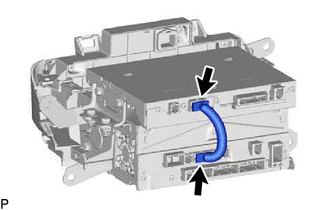
18. REMOVE NO. 1 NAVIGATION WIRE
| (a) Disconnect the 2 connectors to remove the No. 1 navigation wire. |
|
19. REMOVE NAVIGATION ECU WITH BRACKET
| (a) Remove the 2 screws. |
|
.png)
| (b) Remove the 2 screws. |
|
.png)
(c) Disengage the 4 claws and remove the navigation ECU with bracket as shown in the illustration.
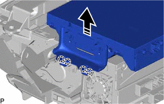
.png) | Remove in this Direction |
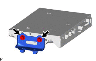
20. REMOVE NO. 1 RADIO RECEIVER BRACKET
| (a) Remove the 2 screws and No. 1 radio receiver bracket. |
|
21. REMOVE NAVIGATION ECU
READ NEXT:
 Removal
REMOVAL PROCEDURE 1. PRECAUTION (for HV Model) NOTICE:
When replacing the radio receiver assembly or navigation ECU, always replace it with a new one. If a radio receiver assembly or navigation ECU
"No GPS signal" mark is displayed
CAUTION / NOTICE / HINT NOTICE:
Depending on the parts that are replaced during vehicle inspection or maintenance, performing initialization, registration or calibration may be needed. Refer to Pre
SEE MORE:
Shift Paddle Switch
ComponentsCOMPONENTS ILLUSTRATION *1 NO. 1 SWITCH WIRE *2 SHIFT PADDLE SWITCH (TRANSMISSION SHIFT SWITCH ASSEMBLY) *3 STEERING PAD SWITCH ASSEMBLY *4 STEERING WHEEL ASSEMBLY *5 SHIFT PADDLE SWITCH LH (TRANSMISSION SHIFT SWITCH ASSEMBLY) *6 SHIFT PADDLE SWITCH RH (TRANS
Diagnostic Trouble Code Chart
DIAGNOSTIC TROUBLE CODE CHART Power Mirror Control System (w/ Memory) DTC No. Detection Item Link U0142 Lost Communication with Main Body ECU
