Lexus ES: Installation
INSTALLATION
PROCEDURE
1. INSTALL REAR BUMPER ASSEMBLY
(a) w/ Wire Harness:
(1) Connect the connector.
(b) Engage the 6 claws as shown in the illustration.
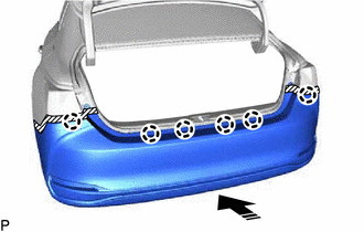
.png) | Install in this Direction |
(c) Engage the 6 claws as shown in the illustration.
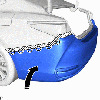
| | Install in this Direction |
HINT:
Use the same procedure for the RH side and LH side.
(d) Install the 12 clips.
(e) Install the screw.
HINT:
Use the same procedure for the RH side and LH side.
(f) Engage the 2 claws.
HINT:
Use the same procedure for the RH side and LH side.
(g) Install the clip.
HINT:
Use the same procedure for the RH side and LH side.
(h) Install the rear bumper assembly with the 2 screws.
2. INSTALL REAR COMBINATION LIGHT COVER LH
Click here .gif)
3. INSTALL REAR COMBINATION LIGHT COVER RH
HINT:
Use the same procedure as for the LH side.
4. CONNECT CABLE TO NEGATIVE AUXILIARY BATTERY TERMINAL (w/ Hands Free Power Trunk Lid)
Click here
5. INITIALIZE KICK DOOR CONTROL SENSOR (w/ Hands Free Power Trunk Lid)
Click here
6. INSPECT KICK DOOR CONTROL SENSOR (w/ Hands Free Power Trunk Lid)
Click here
7. PERFORM CALIBRATION (w/ Parking Support Brake System)
Click here
READ NEXT:
 Components
COMPONENTS ILLUSTRATION *1 COURTESY LIGHT ASSEMBLY *2 REAR DOOR TRIM BOARD SUB-ASSEMBLY *3 REAR DOOR UPPER TRIM PAD *4 REAR POWER WINDOW REGULATOR SWITCH ASSEMBLY WITH REAR DOOR UP
Removal
REMOVAL CAUTION / NOTICE / HINT The necessary procedures (adjustment, calibration, initialization, or registration) that must be performed after parts are removed and installed, or replaced during rea
SEE MORE:
Internal Control Module Random Access Memory (RAM) Error Data Memory Failure (P060444)
MONITOR DESCRIPTION The ECM continuously monitors its internal memory status. This self-check ensures that the ECM is functioning properly. The ECM memory status is diagnosed by internal mirroring of the main CPU and sub CPU to detect Random Access Memory (RAM) errors. If outputs from these CPUs are
Data List / Active Test
DATA LIST / ACTIVE TEST DATA LIST NOTICE: In the table below, the values listed under "Normal Condition" are reference values. Do not depend solely on these reference values when deciding whether a part is faulty or not. HINT: Using the Techstream to read the Data List allows the values or states of
