Lexus ES: Components
Lexus ES (XZ10) Service Manual / Vehicle Interior / Door / Hatch / Fuel Lid Opener Switch / Components
COMPONENTS
ILLUSTRATION
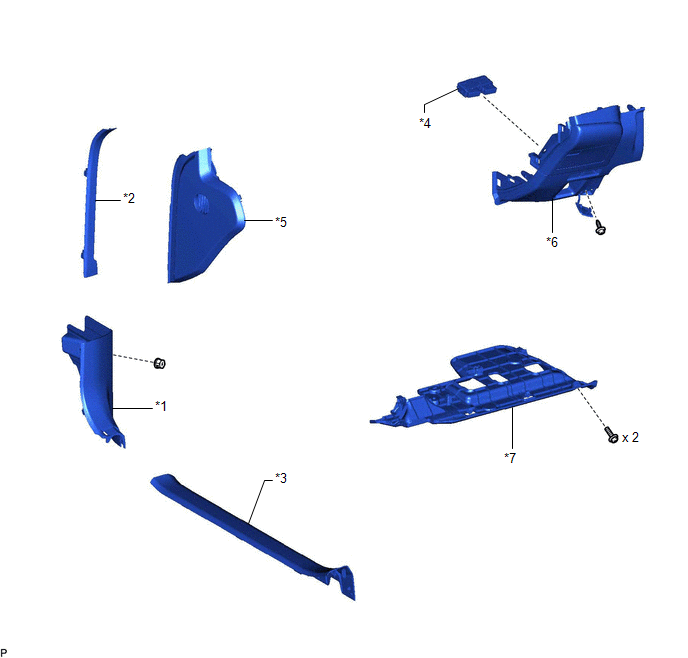
| *1 | COWL SIDE TRIM BOARD LH | *2 | FRONT DOOR OPENING TRIM COVER LH |
| *3 | FRONT DOOR SCUFF PLATE LH | *4 | FUEL LID OPENER SWITCH (TRUNK AND FUEL SWITCH ASSEMBLY) |
| *5 | INSTRUMENT SIDE PANEL LH | *6 | LOWER INSTRUMENT PANEL FINISH PANEL SUB-ASSEMBLY |
| *7 | NO. 1 INSTRUMENT PANEL UNDER COVER SUB-ASSEMBLY | - | - |
READ NEXT:
 Removal
REMOVAL PROCEDURE 1. REMOVE FRONT DOOR SCUFF PLATE LH Click here 2. REMOVE COWL SIDE TRIM BOARD LH Click here 3. REMOVE FRONT DOOR OPENING TRIM COVER LH Click here 4. REMOVE INSTRUMENT SIDE P
Inspection
INSPECTION PROCEDURE 1. INSPECT FUEL LID OPENER SWITCH (TRUNK AND FUEL SWITCH ASSEMBLY) (a) Check the switch. (1) Measure the resistance according to the value(s) in the table below. Standard Resis
Installation
INSTALLATION PROCEDURE 1. INSTALL FUEL LID OPENER SWITCH (TRUNK AND FUEL SWITCH ASSEMBLY) (a) Engage the 2 claws to install the fuel lid opener switch (trunk and fuel switch assembly) as shown in the
SEE MORE:
Right Rear Wheel ABS Hold Solenoid Control Circuit Short to Battery (C12E712,...,C12F249)
DESCRIPTION The ABS solenoid relay and solenoid valves are built into the brake actuator assembly. The rear solenoid valve RH controls the brake fluid pressure of the rear wheel cylinder RH of the vehicle. When this DTC is stored, the fail-safe function operates and the ABS solenoid relay is turned
Millimeter Wave Radar Sensor Communication Stop Mode
DESCRIPTION Detection Item Symptom Trouble Area Millimeter Wave Radar Sensor Communication Stop Mode Any of the following conditions are met:
Communication stop for "Front Radar" is indicated on the "Communication Bus Check" screen of the Techstream.
Click here
Communication st
© 2016-2026 Copyright www.lexguide.net
