Lexus ES: Parts Location
PARTS LOCATION
ILLUSTRATION
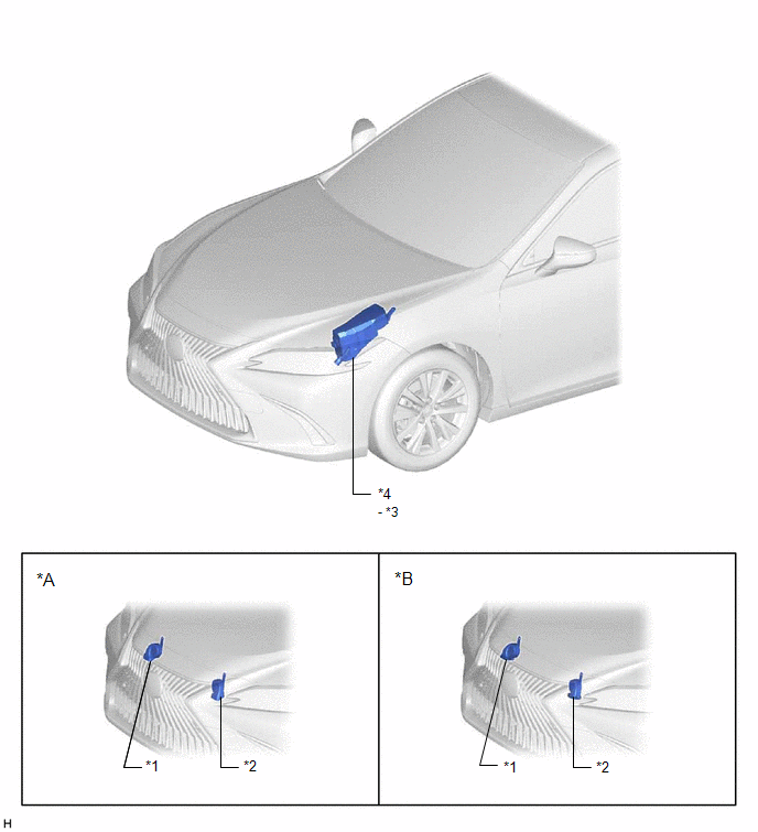
| *A | for Type A | *B | for Type B |
| *1 | HIGH PITCHED HORN ASSEMBLY | *2 | LOW PITCHED HORN ASSEMBLY |
| *3 | HORN RELAY | *4 | ENGINE ROOM RELAY BLOCK AND JUNCTION BLOCK ASSEMBLY - HORN FUSE |
ILLUSTRATION
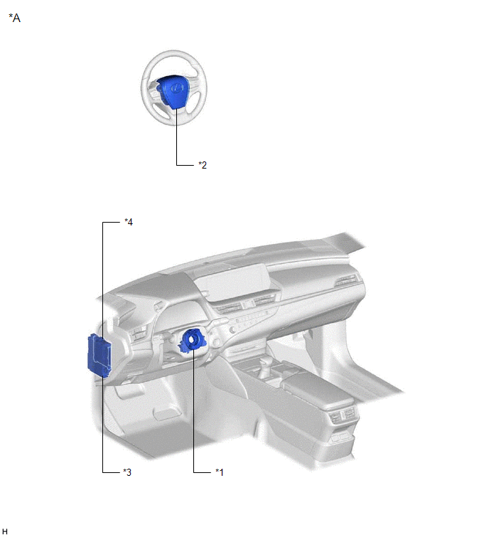
| *A | for LHD | - | - |
| *1 | SPIRAL CABLE SUB-ASSEMBLY | *2 | HORN BUTTON ASSEMBLY |
| *3 | INSTRUMENT PANEL JUNCTION BLOCK ASSEMBLY | *4 | MAIN BODY ECU (MULTIPLEX NETWORK BODY ECU) |
READ NEXT:
 Precaution
PRECAUTION PRECAUTION FOR DISCONNECTING CABLE FROM NEGATIVE AUXILIARY BATTERY TERMINAL NOTICE: When disconnecting the cable from the negative (-) auxiliary battery terminal, initialize the following s
Problem Symptoms Table
PROBLEM SYMPTOMS TABLE NOTICE: Before replacing the main body ECU (multiplex network body ECU), refer to Registration. for Gasoline Model: Click here for HV Model: Click here HINT: Use the tabl
System Diagram
SYSTEM DIAGRAM
SEE MORE:
Dtc Check / Clear
DTC CHECK / CLEAR CHECK FOR DTC (a) Connect the Techstream to the DLC3. (b) Turn the engine switch on (IG). (c) Turn the Techstream on. (d) Enter the following menus: Body Electrical / (desired system) / Trouble Codes. Body Electrical > Wiper > Trouble Codes Body Electrical > Main Body >
Front Left Microphone Circuit Component Internal Failure (B1AA296,B1AA31C)
DESCRIPTION These DTCs are stored when a malfunction occurs in the No. 1 active noise control microphone system. DTC No. Detection Item DTC Detection Condition Trouble Area B1AA296 Front Left Microphone Circuit Component Internal Failure Stereo component equalizer assembly detects m
© 2016-2026 Copyright www.lexguide.net
