Lexus ES: Installation
INSTALLATION
CAUTION / NOTICE / HINT
HINT:
- Use the same procedure for the RH side and LH side.
- The following procedure is for the LH side.
PROCEDURE
1. INSTALL REAR SUSPENSION SUPPORT ASSEMBLY
(a) Secure the rear suspension support assembly in a vise using aluminum plates.
NOTICE:
Do not overtighten the vise.
(b) Install the rear suspension support assembly to the rear shock absorber assembly.
(c) Apply a few drops of adhesive to the threads of a new rear support to rear shock absorber nut.
Adhesive:
Toyota Genuine Adhesive 1324, Three Bond 1324 or equivalent
NOTICE:
Only apply adhesive to the nut if it is not supplied as a precoated part.
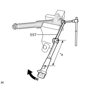
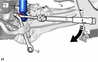
| (d) Using SST and a 6 mm hexagon socket wrench, hold the rear shock absorber rod and tighten the rear support to rear shock absorber nut. SST: 09729-00170 Torque: Specified tightening torque : 25 N·m {255 kgf·cm, 18 ft·lbf} NOTICE: Securely insert the 6 mm hexagon socket wrench into the rear shock absorber rod to prevent damage to the rear shock absorber assembly when tightening the rear support to rear shock absorber nut. HINT:
|
|
2. INSTALL REAR SHOCK ABSORBER CAP
(a) Install the rear shock absorber cap to the rear shock absorber assembly.
3. TEMPORARILY INSTALL REAR SHOCK ABSORBER ASSEMBLY
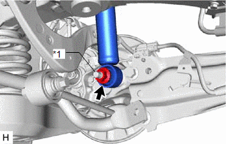
| (a) Temporarily install the rear shock absorber assembly to the rear axle carrier sub-assembly with the nut and plate washer. NOTICE: Hold the rear axle carrier pin while rotating the nut. |
|
4. STABILIZE SUSPENSION
(a) Using a jack and wooden block, apply load to the suspension so that the rear No. 2 suspension arm assembly is positioned as shown in the illustration.
Standard Length (A):
13 mm (0.512 in.)
CAUTION:
Do not jack up the rear No. 2 suspension arm assembly too high as the vehicle may fall.
NOTICE:
- When jacking up the rear No. 2 suspension arm assembly, be sure to jack it up slowly.
- Make sure to perform this operation with the vehicle kept as low as possible.
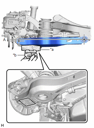
| *a | Wooden Block |
| *b | Jack |
.png) | Wooden Block Placement Location |
5. INSTALL REAR UPPER CONTROL ARM ASSEMBLY
(a) Install the rear upper control arm assembly to the rear axle carrier sub-assembly with the bolt and nut.
Torque:
73 N·m {744 kgf·cm, 54 ft·lbf}
NOTICE:
- Insert the bolt with the threaded end facing the rear of the vehicle.
- Because the nut has its own stopper, do not turn the nut. Tighten the bolt with the nut secured.
6. CONNECT REAR SHOCK ABSORBER ASSEMBLY
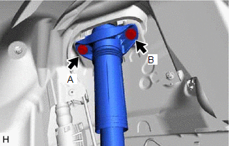
| (a) Connect the rear shock absorber assembly to the vehicle with the 2 bolts. Torque: 55 N·m {561 kgf·cm, 41 ft·lbf} NOTICE: Temporarily tighten the bolt (A) and then fully tighten the 2 bolts in the order of (B) and (A). |
|
7. INSTALL REAR SHOCK ABSORBER ASSEMBLY
| (a) Using a ball joint lock nut wrench fully tighten the rear shock absorber assembly with the nut. Torque: Specified tightening torque : 125 N·m {1275 kgf·cm, 92 ft·lbf} NOTICE: Hold the rear axle carrier pin while rotating the nut. HINT:
|
|
8. INSTALL REAR STABILIZER LINK ASSEMBLY
Click here .gif)
9. INSTALL NO. 2 PARKING BRAKE WIRE ASSEMBLY (w/ AVS)
| (a) Engage the guide and install the wire harness bracket. |
|

(b) Install the nut.
Torque:
8.5 N·m {87 kgf·cm, 75 in·lbf}
(c) Engage the clamp and install the No. 2 parking brake wire assembly to the wire harness bracket.
| (d) Connect the connector. |
|
.png)
10. INSTALL NO. 1 FLOOR UNDER COVER (for Gasoline Model)
(a) for RH Side:
Click here
11. INSTALL NO. 2 FLOOR UNDER COVER (for Gasoline Model)
(a) for LH Side:
Click here
12. INSTALL REAR HEIGHT CONTROL SENSOR SUB-ASSEMBLY LH (w/ Height Control Sensor)
(a) for LH Side:
Click here
13. INSTALL REAR WHEEL
Click here
14. INSPECT AND ADJUST REAR WHEEL ALIGNMENT
Click here
15. PERFORM INITIALIZATION
for HV Model:| *1: for LED type turn signal light | |
| |
| Parking Assist Monitor System | |
| Panoramic View Monitor System | |
| Lighting System*1 | |
| *1: for LED type turn signal light | |
| |
| Parking Assist Monitor System | |
| Panoramic View Monitor System | |
| Lighting System*1 | |
READ NEXT:
 Installation
INSTALLATION CAUTION / NOTICE / HINT HINT:
Use the same procedure for the RH side and LH side.
The following procedure is for the LH side.
PROCEDURE 1. INSTALL REAR SUSPENSION SUPPORT ASSEMBLY
Disposal
DISPOSAL PROCEDURE 1. DISPOSE OF REAR SHOCK ABSORBER ASSEMBLY CAUTION:
Always use a cloth to prevent shards of metal from flying about due to the release of pressurized gas.
Always wear safety gl
SEE MORE:
Slave Module Horizontal Axis Misalignment (C1AC2)
DESCRIPTION This DTC is stored when the angle of the blind spot monitor sensor LH deviates more than the allowable range from the horizontal axis. HINT:
If a drum tester such as a speedometer tester, brake/speedometer combination tester or chassis dynamometer is used with the blind spot monitor s
Precaution
PRECAUTION PRECAUTION FOR DISCONNECTING CABLE FROM NEGATIVE BATTERY TERMINAL NOTICE: When disconnecting the cable from the negative (-) battery terminal, initialize the following system(s) after the cable is reconnected: System See Procedure Lane Control System Pre-collision Syst
