Lexus ES: Installation
INSTALLATION
CAUTION / NOTICE / HINT
HINT:
- Use the same procedure for the RH side and LH side.
- The following procedure is for the LH side.
PROCEDURE
1. TEMPORARILY INSTALL REAR NO. 1 SUSPENSION ARM ASSEMBLY
(a) Temporarily install the rear No. 1 suspension arm assembly to the rear axle carrier sub-assembly and rear suspension member sub-assembly with the 2 bolts and 2 nuts.
NOTICE:
- Because the nut has its own stopper, do not turn the nut. Tighten the bolt with the nut secured.
- Insert the bolt with the threaded end facing the rear of the vehicle.
2. TEMPORARILY INSTALL REAR NO. 2 SUSPENSION ARM ASSEMBLY
(a) Temporarily install the rear No. 2 suspension arm assembly to the rear suspension member sub-assembly with the No. 2 camber adjust cam, rear suspension toe adjust cam sub-assembly and nut.
NOTICE:
- Insert the rear suspension toe adjust cam sub-assembly from the rear of the vehicle.
- When tightening the nut, keep the rear suspension toe adjust cam sub-assembly from rotating.
3. INSTALL REAR LOWER COIL SPRING INSULATOR
Click here .gif)
4. INSTALL REAR COIL SPRING
Click here
5. STABILIZE SUSPENSION
Click here
6. INSTALL REAR STABILIZER LINK ASSEMBLY
for 2WD: Click here
for AWD: Click here
7. INSTALL REAR NO. 1 SUSPENSION ARM ASSEMBLY (for 2WD)
| (a) Install the rear No. 1 suspension arm assembly with the 2 bolts. Torque: 73 N·m {744 kgf·cm, 54 ft·lbf} NOTICE: Because the nut has its own stopper, do not turn the nut. Tighten the bolt with the nut secured. |
|
.png)
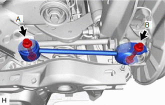
8. INSTALL REAR NO. 1 SUSPENSION ARM ASSEMBLY (for AWD)
| (a) Install the rear No. 1 suspension arm assembly with the 2 bolts. Torque: Bolt A : 115 N·m {1173 kgf·cm, 85 ft·lbf} Bolt B : 73 N·m {744 kgf·cm, 54 ft·lbf} NOTICE: Because the nut has its own stopper, do not turn the nut. Tighten the bolt with the nut secured. |
|
9. INSTALL REAR NO. 2 SUSPENSION ARM ASSEMBLY
| (a) Install the rear No. 2 suspension arm assembly (rear axle carrier sub-assembly side) with the bolt. Torque: 73 N·m {744 kgf·cm, 54 ft·lbf} NOTICE: Because the nut has its own stopper, do not turn the nut. Tighten the bolt with the nut secured. |
|
.png)
10. INSTALL NO. 1 FLOOR UNDER COVER (for Gasoline Model 2WD)
(a) for RH Side:
Click here
11. INSTALL NO. 2 FLOOR UNDER COVER (for Gasoline Model 2WD)
(a) for LH Side:
Click here
12. INSTALL REAR HEIGHT CONTROL SENSOR SUB-ASSEMBLY LH (w/ Height Control Sensor)
(a) for LH Side:
Click here
13. INSTALL REAR WHEEL
Click here
14. INSTALL REAR NO. 2 SUSPENSION ARM ASSEMBLY
(a) Lower the vehicle to the ground.
(b) Bounce the vehicle up and down at the corners to stabilize the rear suspension.
| (c) Align the matchmarks on the No. 2 camber adjust cam, rear suspension toe adjust cam sub-assembly and rear suspension member sub-assembly. |
|
.png)
(d) Fully tighten the nut.
Torque:
100 N·m {1020 kgf·cm, 74 ft·lbf}
NOTICE:
- Hold the rear suspension toe adjust cam sub-assembly while rotating the nut.
- Make sure that the vehicle is unloaded when fully tightening the nut.
15. INSPECT AND ADJUST REAR WHEEL ALIGNMENT
Click here
16. PERFORM INITIALIZATION
for HV Model:| *1: for LED type turn signal light | |
| |
| Parking Assist Monitor System | |
| Panoramic View Monitor System | |
| Lighting System*1 | |
| *1: for LED type turn signal light | |
| |
| Parking Assist Monitor System | |
| Panoramic View Monitor System | |
| Lighting System*1 | |
READ NEXT:
 Components
COMPONENTS ILLUSTRATION *A for Gasoline Model *B for RH Side *C for LH Side - - *1 NO. 1 FLOOR UNDER COVER *2 NO. 2 FLOOR UNDER COVER N*m (kgf*cm, ft.*lbf): Specif
Components
COMPONENTS ILLUSTRATION *A for Gasoline Model 2WD *B for RH Side *C for LH Side - - *1 NO. 1 FLOOR UNDER COVER *2 NO. 2 FLOOR UNDER COVER N*m (kgf*cm, ft.*lbf): Sp
SEE MORE:
Certification ECU Vehicle Information Reading/Writing Process Malfunction (B15F7)
DESCRIPTION This DTC is stored when items controlled by the certification ECU (smart key ECU assembly) cannot be customized via the navigation system vehicle customization screen. HINT: The certification ECU (smart key ECU assembly) controls the smart access system with push-button start (for Entry
Components
COMPONENTS ILLUSTRATION *A for Driver Side *B for Front Passenger Side *1 COURTESY LIGHT ASSEMBLY *2 FRONT DOOR TRIM BOARD SUB-ASSEMBLY *3 MULTIPLEX NETWORK MASTER SWITCH ASSEMBLY WITH FRONT DOOR UPPER ARMREST BASE PANEL *4 NO. 2 DOOR TRIM PAD *5 OUTER MIRROR CONT
