Lexus ES: Components
COMPONENTS
ILLUSTRATION
.png)
| *A | for Gasoline Model 2WD | *B | for RH Side |
| *C | for LH Side | - | - |
| *1 | NO. 1 FLOOR UNDER COVER | *2 | NO. 2 FLOOR UNDER COVER |
.png) | N*m (kgf*cm, ft.*lbf): Specified torque | - | - |
ILLUSTRATION
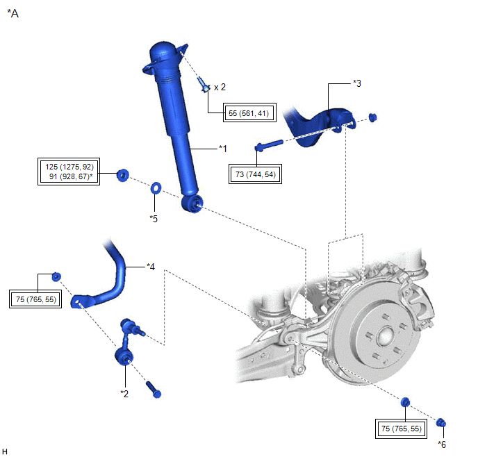
| *A | for 2WD without AVS | - | - |
| *1 | REAR SHOCK ABSORBER ASSEMBLY | *2 | REAR STABILIZER LINK ASSEMBLY |
| *3 | REAR UPPER CONTROL ARM ASSEMBLY | *4 | REAR STABILIZER BAR |
| *5 | PLATE WASHER | *6 | CAP |
.png) | Tightening torque for "Major areas involving basic vehicle performance such as moving/turning/stopping": N*m (kgf*cm, ft.*lbf) | * | For use with a ball joint lock nut wrench |
ILLUSTRATION
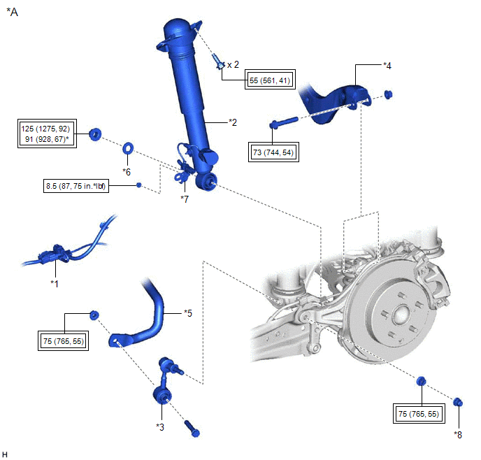
| *A | for 2WD with AVS | - | - |
| *1 | NO. 2 PARKING BRAKE WIRE ASSEMBLY | *2 | REAR SHOCK ABSORBER ASSEMBLY |
| *3 | REAR STABILIZER LINK ASSEMBLY | *4 | REAR UPPER CONTROL ARM ASSEMBLY |
| *5 | REAR STABILIZER BAR | *6 | PLATE WASHER |
| *7 | WIRE HARNESS BRACKET | *8 | CAP |
| | Tightening torque for "Major areas involving basic vehicle performance such as moving/turning/stopping": N*m (kgf*cm, ft.*lbf) | | N*m (kgf*cm, ft.*lbf): Specified torque |
| * | For use with a ball joint lock nut wrench | - | - |
ILLUSTRATION
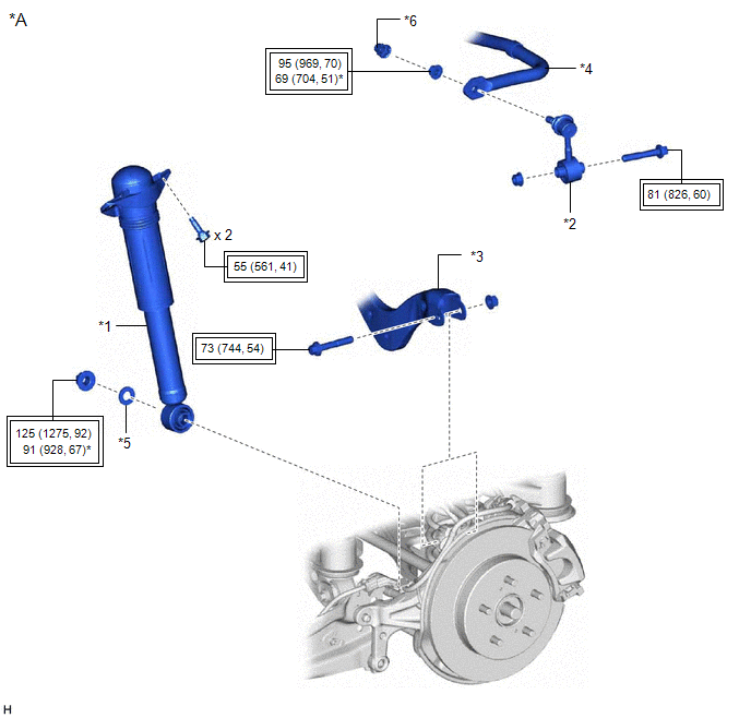
| *A | for AWD | - | - |
| *1 | REAR SHOCK ABSORBER ASSEMBLY | *2 | REAR STABILIZER LINK ASSEMBLY |
| *3 | REAR UPPER CONTROL ARM ASSEMBLY | *4 | REAR STABILIZER BAR |
| *5 | PLATE WASHER | *6 | CAP |
| | Tightening torque for "Major areas involving basic vehicle performance such as moving/turning/stopping": N*m (kgf*cm, ft.*lbf) | * | For use with a ball joint lock nut wrench |
ILLUSTRATION
.png)
| *1 | REAR SHOCK ABSORBER ASSEMBLY | *2 | REAR SHOCK ABSORBER CAP |
| *3 | REAR SUSPENSION SUPPORT ASSEMBLY | *4 | REAR SUPPORT TO REAR SHOCK ABSORBER NUT |
| | Tightening torque for "Major areas involving basic vehicle performance such as moving/turning/stopping": N*m (kgf*cm, ft.*lbf) | * | For use with SST |
| ● | Non-reusable part | .png) | Adhesive 1324 |
| ★ | Precoated part | - | - |
READ NEXT:
 Removal
REMOVAL CAUTION / NOTICE / HINT The necessary procedures (adjustment, calibration, initialization, or registration) that must be performed after parts are removed and installed, or replaced during rea
Removal
REMOVAL CAUTION / NOTICE / HINT The necessary procedures (adjustment, calibration, initialization, or registration) that must be performed after parts are removed and installed, or replaced during rea
Inspection
INSPECTION PROCEDURE 1. INSPECT REAR SHOCK ABSORBER ASSEMBLY (a) Compress and extend the rear shock absorber assembly rod 4 or more times. Standard: When compressed and extended at a constant speed,
SEE MORE:
Replacement
REPLACEMENT
CAUTION / NOTICE / HINT
CAUTION:
Do not remove the radiator cap sub-assembly or radiator drain cock plug while
the engine and radiator assembly are still hot. Pressurized, hot engine coolant
and steam may be released and cause serious burns.
PROCEDURE
1. DRAIN ENGINE COOLANT
Drive Motor "A" Circuit Current Out of Range (P0BFF1D)
DTC SUMMARY MALFUNCTION DESCRIPTION This DTC is stored when the motor generator control system is malfunctioning and current does not flow as commanded. The cause of this malfunction may be one of the following: Area Main Malfunction Description Inside of inverter Inverter with converter
