Lexus ES: Components
COMPONENTS
ILLUSTRATION
.png)
| *A | for Gasoline Model | *B | for RH Side |
| *C | for LH Side | - | - |
| *1 | NO. 1 FLOOR UNDER COVER | *2 | NO. 2 FLOOR UNDER COVER |
.png) | N*m (kgf*cm, ft.*lbf): Specified torque | - | - |
ILLUSTRATION
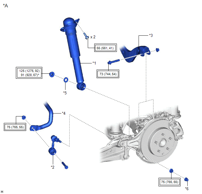
| *A | w/o AVS | - | - |
| *1 | REAR SHOCK ABSORBER ASSEMBLY | *2 | REAR STABILIZER LINK ASSEMBLY |
| *3 | REAR UPPER CONTROL ARM ASSEMBLY | *4 | REAR STABILIZER BAR |
| *5 | PLATE WASHER | *6 | CAP |
.png) | Tightening torque for "Major areas involving basic vehicle performance such as moving/turning/stopping": N*m (kgf*cm, ft.*lbf) | * | For use with a ball joint lock nut wrench |
ILLUSTRATION
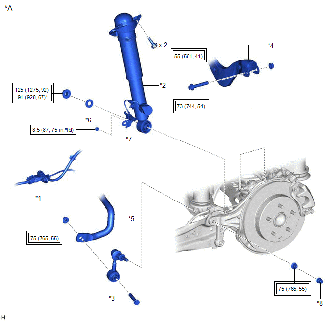
| *A | w/ AVS | - | - |
| *1 | NO. 2 PARKING BRAKE WIRE ASSEMBLY | *2 | REAR SHOCK ABSORBER ASSEMBLY |
| *3 | REAR STABILIZER LINK ASSEMBLY | *4 | REAR UPPER CONTROL ARM ASSEMBLY |
| *5 | REAR STABILIZER BAR | *6 | PLATE WASHER |
| *7 | WIRE HARNESS BRACKET | *8 | CAP |
| | Tightening torque for "Major areas involving basic vehicle performance such as moving/turning/stopping": N*m (kgf*cm, ft.*lbf) | | N*m (kgf*cm, ft.*lbf): Specified torque |
| * | For use with a ball joint lock nut wrench | - | - |
ILLUSTRATION

| *1 | REAR SHOCK ABSORBER ASSEMBLY | *2 | REAR SHOCK ABSORBER CAP |
| *3 | REAR SUSPENSION SUPPORT ASSEMBLY | *4 | REAR SUPPORT TO REAR SHOCK ABSORBER NUT |
| | Tightening torque for "Major areas involving basic vehicle performance such as moving/turning/stopping": N*m (kgf*cm, ft.*lbf) | * | For use with SST |
| ● | Non-reusable part | .png) | Adhesive 1324 |
| ★ | Precoated part | - | - |
READ NEXT:
 Components
COMPONENTS ILLUSTRATION *A for Gasoline Model 2WD *B for RH Side *C for LH Side - - *1 NO. 1 FLOOR UNDER COVER *2 NO. 2 FLOOR UNDER COVER N*m (kgf*cm, ft.*lbf): Sp
Removal
REMOVAL CAUTION / NOTICE / HINT The necessary procedures (adjustment, calibration, initialization, or registration) that must be performed after parts are removed and installed, or replaced during rea
Removal
REMOVAL CAUTION / NOTICE / HINT The necessary procedures (adjustment, calibration, initialization, or registration) that must be performed after parts are removed and installed, or replaced during rea
SEE MORE:
Horn
ComponentsCOMPONENTS ILLUSTRATION *1 COOL AIR INTAKE DUCT SEAL *2 HIGH PITCHED HORN ASSEMBLY *3 LOW PITCHED HORN ASSEMBLY - - N*m (kgf*cm, ft.*lbf): Specified torque - - RemovalREMOVAL PROCEDURE 1. REMOVE COOL AIR INTAKE DUCT SEAL Click here 2. REMOVE HIGH PITC
Operation Check
OPERATION CHECK PKSB OFF INDICATOR LIGHT OPERATION CHECK (a) Turn the engine switch on (IG). (b) Turn the parking support brake system off and confirm that the PKSB OFF indicator in the combination meter illuminates. HINT: If the parking support brake system is not set to off in the customize setti
