Lexus ES: Installation
INSTALLATION
PROCEDURE
1. INSTALL BATTERY ECU ASSEMBLY
CAUTION:
Be sure to wear insulated gloves and protective goggles.
(a) Install the battery ECU assembly to the HV battery with the 3 nuts.
Torque:
7.5 N·m {76 kgf·cm, 66 in·lbf}
NOTICE:
-
Check color of the label.
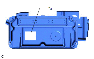
*a
Black Label
- If the battery ECU assembly has been struck or dropped, replace it.
| (b) Connect the 3 battery ECU assembly connectors and move the lock lever to lock them. NOTICE: Make sure that the connectors are connected securely. |
|
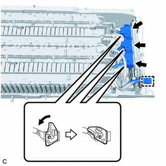
(c) Engage the clamp.
2. INSTALL NO. 1 HV BATTERY HOSE
CAUTION:
Be sure to wear insulated gloves and protective goggles.
(a) Engage the 2 claws to install the No. 1 HV battery hose to the HV battery.
(b) Engage the 2 clips.
3. INSTALL UPPER HV BATTERY COVER SUB-ASSEMBLY
CAUTION:
Be sure to wear insulated gloves and protective goggles.
(a) Install the upper HV battery cover sub-assembly to the HV battery with the 5 bolts and 7 nuts.
Torque:
7.5 N·m {76 kgf·cm, 66 in·lbf}
4. CONNECT FLOOR WIRE
Click here .gif)
5. INSTALL NO. 4 HV BATTERY PROTECTOR
Click here
6. CONNECT FLOOR WIRE
Click here
7. INSTALL HYBRID BATTERY HOSE ASSEMBLY
Click here
8. INSTALL NO. 1 HV BATTERY COVER PANEL RH
Click here
9. INSTALL REAR SEAT CUSHION LEG SUB-ASSEMBLY
Click here
10. INSTALL REAR UNDER COVER
Click here
11. INSTALL REAR UNDER SIDE COVER LH
Click here
12. INSTALL REAR DOOR SCUFF PLATE LH
Click here
13. INSTALL REAR UNDER SIDE COVER RH
Click here
14. INSTALL REAR DOOR SCUFF PLATE RH
HINT:
Use the same procedure as for the LH side.
15. INSTALL NO. 2 INDOOR ELECTRICAL KEY ANTENNA ASSEMBLY
Click here
16. INSTALL SERVICE PLUG GRIP
Click here
17. PERFORM INITIALIZATION
Click here
READ NEXT:
 Components
COMPONENTS ILLUSTRATION *1 BATTERY SERVICE HOLE COVER *2 SERVICE PLUG GRIP ILLUSTRATION *1 CONNECTOR COVER ASSEMBLY *2 ENGINE ROOM MAIN WIRE Tightening torque for "Major
Inspection
INSPECTION PROCEDURE 1. INSPECT ELECTRIC VEHICLE BATTERY PLUG ASSEMBLY (a) Measure the resistance according to the value(s) in the table below. Standard Resistance: Tester Connection Conditio
SEE MORE:
Precaution
PRECAUTION PRECAUTION FOR DISCONNECTING CABLE FROM NEGATIVE BATTERY TERMINAL NOTICE: When disconnecting the cable from the negative (-) battery terminal, initialize the following systems after the cable is reconnected. System Name See Procedure Lane Control System (for Gasoline Model)
Components
COMPONENTS ILLUSTRATION *A w/ Dust Cap - - *1 FUEL PRESSURE SENSOR (FUEL DELIVERY PIPE WITH SENSOR ASSEMBLY LH) *2 FUEL PIPE PLUG SUB-ASSEMBLY *3 DUST CAP SUB-ASSEMBLY *4 O-RING *5 NO. 1 FUEL INJECTOR BACK-UP RING *6 NO. 2 FUEL INJECTOR BACK-UP RING *7 N
