Lexus ES: Removal
REMOVAL
CAUTION / NOTICE / HINT
The necessary procedures (adjustment, calibration, initialization or registration) that must be performed after parts are removed and installed, or replaced during front exhaust pipe assembly (TWC: Rear Catalyst), center exhaust pipe assembly and tail exhaust pipe assembly removal/installation are shown below.
Necessary Procedures After Parts Removed/Installed/Replaced| Replaced Part or Performed Procedure | Necessary Procedure | Effect/Inoperative Function when Necessary Procedure not Performed | Link |
|---|---|---|---|
| Inspection After Repair |
| |
CAUTION:
To prevent burns, do not touch the engine, exhaust pipe or other high temperature components while the engine is hot.
.png)
PROCEDURE
1. REMOVE TAIL EXHAUST PIPE ASSEMBLY LH
CAUTION:
To prevent burns, do not touch the engine, exhaust pipe or other high temperature components while the engine is hot.
| (a) Remove the 2 bolts and disconnect the tail exhaust pipe assembly LH from the center exhaust pipe assembly. |
|
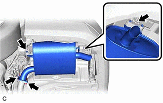
(b) Remove the tail exhaust pipe assembly LH from the 2 exhaust pipe supports.
(c) Remove the gasket from the center exhaust pipe assembly.
2. REMOVE CENTER EXHAUST PIPE ASSEMBLY
CAUTION:
To prevent burns, do not touch the engine, exhaust pipe or other high temperature components while the engine is hot.
| (a) Remove the 2 bolts and disconnect the center exhaust pipe assembly from the front exhaust pipe assembly (TWC: Rear Catalyst). |
|
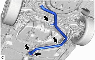
(b) Remove the center exhaust pipe assembly from the 2 exhaust pipe supports.
(c) Remove the gasket from the front exhaust pipe assembly (TWC: Rear Catalyst).
3. REMOVE FRONT FLOOR COVER LH
| (a) Type A: (1) Remove the 4 bolts and 4 clips (A). (2) Disengage the grommet (B) and 6 clips (C) to remove the front floor cover LH. |
|
.png)
| (b) Type B: (1) Remove the 3 bolts and 4 clips (A). (2) Disengage the grommet (B) and 6 clips (C) to remove the front floor cover LH. |
|
.png)
4. REMOVE FRONT FLOOR COVER RH
(a) Type A:
| (1) Remove the 3 bolts and 4 clips (A). |
|
.png)
(2) Disengage the grommet (B) and 6 clips (C) to remove the front floor cover RH.
(b) Type B:
| (1) Remove the 4 bolts and 4 clips (A). |
|
.png)
(2) Disengage the grommet (B) and 6 clips (C) to remove the front floor cover RH.
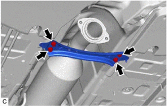
5. REMOVE FRONT CENTER FLOOR BRACE
| (a) Remove the 4 bolts and front center floor brace from the vehicle body. |
|
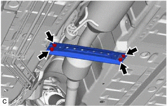
6. REMOVE CENTER FLOOR CROSSMEMBER BRACE
| (a) Remove the 4 bolts and center floor crossmember brace from the vehicle body. |
|
7. REMOVE AIR FUEL RATIO SENSOR (for Sensor 2)
Click here .gif)
8. REMOVE FRONT EXHAUST PIPE ASSEMBLY (TWC: Rear Catalyst)
CAUTION:
To prevent burns, do not touch the engine, exhaust pipe or other high temperature components while the engine is hot.
| (a) Remove the 2 nuts and disconnect the front exhaust pipe assembly (TWC: Rear Catalyst) from the exhaust manifold (TWC: Front Catalyst). |
|
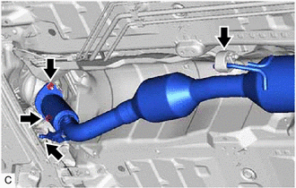
(b) Remove the front exhaust pipe assembly (TWC: Rear Catalyst) from the 2 exhaust pipe supports.
(c) Remove the gasket from the front exhaust pipe assembly (TWC: Rear Catalyst).
READ NEXT:
 Installation
INSTALLATION PROCEDURE 1. INSTALL FRONT EXHAUST PIPE ASSEMBLY (TWC: Rear Catalyst) (a) Install a new gasket to the front exhaust pipe assembly (TWC: Rear Catalyst). (b) Connect the front exhaust pipe
Components
COMPONENTS ILLUSTRATION *A w/ Stud Bolt *B w/o Stud Bolt *1 INTAKE MANIFOLD *2 NO. 1 INTAKE MANIFOLD TO HEAD GASKET *3 NO. 1 ENGINE COVER *4 VACUUM HOSE *5 NO. 2 FU
SEE MORE:
Disassembly
DISASSEMBLY CAUTION / NOTICE / HINT The necessary procedures (adjustment, calibration, initialization or registration) that must be performed after parts are removed and installed, or replaced during engine unit removal/installation are shown below. Necessary Procedure After Parts Removed/Installed/
Front Right Microphone Circuit Component Internal Failure (B1AA696,B1AA71C)
DESCRIPTION These DTCs are stored when a malfunction occurs in the No. 2 active noise control microphone system. DTC No. Detection Item DTC Detection Condition Trouble Area B1AA696 Front Right Microphone Circuit Component Internal Failure Stereo component equalizer assembly detects
