Lexus ES: Installation
INSTALLATION
PROCEDURE
1. INSTALL AIR FUEL RATIO SENSOR
HINT:
Perform "Inspection After Repair" after replacing the air fuel ratio sensor.
Click here .gif)
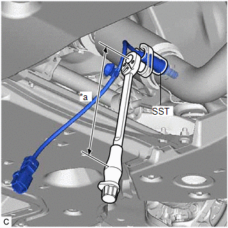
| (a) Using SST, install the air fuel ratio sensor to the front exhaust pipe assembly (TWC: Rear Catalyst). SST: 09224-00012 Torque: Specified tightening torque : 44 N·m {449 kgf·cm, 32 ft·lbf} NOTICE: If the air fuel ratio sensor has been struck or dropped, replace it. HINT:
|
|
(b) Connect the air fuel ratio sensor connector.
(c) Engage the wire harness clamp.
2. INSPECT FOR EXHAUST GAS LEAK
Click here
3. PERFORM INITIALIZATION
(a) Perform "Inspection After Repair" after replacing the air fuel ratio sensor.
Click here
READ NEXT:
 Components
COMPONENTS ILLUSTRATION *1 CAM TIMING OIL CONTROL SOLENOID ASSEMBLY *2 NO. 1 ENGINE COVER SUB-ASSEMBLY *3 O-RING - - N*m (kgf*cm, ft.*lbf): Specified torque ● Non-reus
On-vehicle Inspection
ON-VEHICLE INSPECTION PROCEDURE 1. INSPECT CAM TIMING OIL CONTROL SOLENOID ASSEMBLY (a) Connect the Techstream to the DLC3. (b) Turn the power switch on (IG). (c) Turn the Techstream on. (d) Put the e
SEE MORE:
ECU Malfunction (C1614)
DESCRIPTION This DTC is stored if the parking assist ECU judges that there is an internal malfunction as a result of its self check. HINT: The parking assist ECU stores different types of information during initialization. If the parking assist ECU cannot read the stored information when activated,
Lost Communication with Body Control Module "B" Missing Message (U014287,U015587,U020887)
DESCRIPTION The multiplex tilt and telescopic ECU receives signals from the main body ECU (multiplex network body ECU), combination meter assembly and position control ECU assembly (driver seat) via CAN communication. DTC No. Detection Item DTC Detection Condition Trouble Area U014287
© 2016-2026 Copyright www.lexguide.net
