Lexus ES: Fuel Pressure Sensor
Components
COMPONENTS
ILLUSTRATION
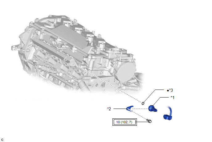
| *1 | NO. 2 FUEL PRESSURE SENSOR | *2 | NO. 2 FUEL PRESSURE SENSOR HOLDER |
| *3 | O-RING | - | - |
.png) | Tightening torque for "Major areas involving basic vehicle performance such as moving/turning/stopping": N*m (kgf*cm, ft.*lbf) | ● | Non-reusable part |
Inspection
INSPECTION
PROCEDURE
1. INSPECT NO. 2 FUEL PRESSURE SENSOR
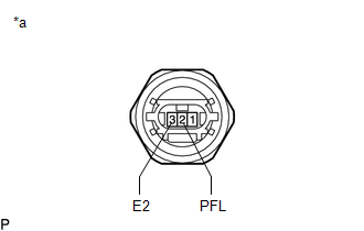
(a) Check the No. 2 fuel pressure sensor output voltage.
| (1) Apply 5 V between terminals 1 (VC) and 3 (E2). NOTICE:
HINT: If a stable power supply is not available, connect 4 nickel-metal hydride batteries (1.2 V each) or equivalent in series. |
|
.png)
| (2) Measure the voltage according to the value(s) in the table below. Standard Voltage:
*: The output voltage changes depending on the voltage applied to the terminals. If the result is not as specified, replace the No. 2 fuel pressure sensor. |
|
Installation
INSTALLATION
CAUTION / NOTICE / HINT
NOTICE:
This procedure includes the installation of small-head bolts. Refer to Small-Head Bolts of Basic Repair Hint to identify the small-head bolts.
Click here .gif)
PROCEDURE
1. INSTALL NO. 2 FUEL PRESSURE SENSOR
HINT:
Perform "Inspection After Repair" after replacing the No. 2 fuel pressure sensor.
Click here
(a) Install a new O-ring to the No. 2 fuel pressure sensor.
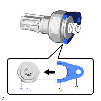
| (b) Install the No. 2 fuel pressure sensor holder to the No. 2 fuel pressure sensor as shown in the illustration. |
|
(c) Using an 8 mm socket wrench, install the No. 2 fuel pressure sensor with the No. 2 fuel pressure sensor holder to the fuel delivery pipe sub-assembly with the bolt.
Torque:
10 N·m {102 kgf·cm, 7 ft·lbf}
(d) Connect the No. 2 fuel pressure sensor connector.
2. INSTALL FUEL (ENGINE ROOM SIDE) PUMP ASSEMBLY
Click here
3. PERFORM INITIALIZATION
(a) Perform "Inspection After Repair" after replacing the No. 2 fuel pressure sensor.
Click here
READ NEXT:
 Components
COMPONENTS ILLUSTRATION *1 FUEL PRESSURE SENSOR *2 NO. 1 FUEL PRESSURE SENSOR HOLDER Tightening torque for "Major areas involving basic vehicle performance such as moving/turning/stop
Inspection
INSPECTION PROCEDURE 1. INSPECT FUEL PRESSURE SENSOR (a) Check the fuel pressure sensor output voltage. (1) Apply 5 V between terminals 1 (VC) and 2 (E2). NOTICE:
Be careful when connecting th
SEE MORE:
System Diagram
SYSTEM DIAGRAM Communication Table Transmitting ECU Receiving ECU Signal Communication Method Certification ECU (smart key ECU assembly) Main body ECU (multiplex network body ECU) Luggage electrical key switch signal CAN Combination meter assembly Main body ECU (multiplex
Components
COMPONENTS ILLUSTRATION *A for 2WD *B for AWD *1 REAR HEIGHT CONTROL SENSOR SUB-ASSEMBLY LH - - N*m (kgf*cm, ft.*lbf): Specified torque - -
