Lexus ES: Inspection
INSPECTION
CAUTION / NOTICE / HINT
NOTICE:
- Make sure the contact surface of the cam timing control motor with EDU assembly (the surface that contacts the No. 2 timing gear cover assembly) is free of foreign matter.
- If the cam timing control motor with EDU assembly has been struck or dropped, replace it.
- Do not disassemble the cam timing control motor with EDU assembly. If disassembled, replace it.
PROCEDURE
1. INSPECT CAM TIMING CONTROL MOTOR WITH EDU ASSEMBLY
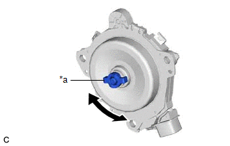
| (a) Rotate the joint of the cam timing control motor with EDU assembly by hand and check that it rotates smoothly. Standard Condition: The joint rotates smoothly. HINT: Due to the magnetic force of the cam timing control motor with EDU assembly the joint may feel as if it is sticking when turning it. If the result is not as specified, replace the cam timing control motor with EDU assembly. |
|
2. INSPECT CAMSHAFT TIMING GEAR ASSEMBLY
NOTICE:
- If the camshaft timing gear assembly has been struck or dropped, replace it.
- Do not disassemble the camshaft timing gear assembly. If disassembled, replace it.
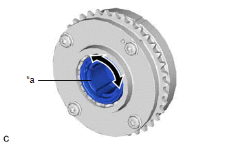
| (a) Rotate the camshaft timing gear assembly eccentric shaft by hand. Standard Condition: The shaft rotates smoothly. HINT:
|
|
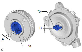
| (b) Inspect the joint clearance. (1) Using a vernier caliper, measure the width (A) of the cutout of the camshaft timing gear assembly eccentric shaft. Standard Width: 5.98 to 6.05 mm (0.235 to 0.238 in.) (2) Using a vernier caliper, measure the width (B) of the joint of the cam timing control motor with EDU assembly. Standard Width: 5.90 to 5.95 mm (0.232 to 0.234 in.) (3) Calculate the clearance by subtracting the width (B) of the joint of the cam timing control motor with EDU assembly from the width (A) of the cutout of the camshaft timing gear assembly eccentric shaft. Standard Clearance: 0.03 to 0.15 mm (0.00118 to 0.00591 in.) Maximum Clearance: 0.7 mm (0.0276 in.) HINT: If the clearance is more than the maximum, replace the camshaft timing gear assembly or cam timing control motor with EDU assembly. |
|
READ NEXT:
 Installation
INSTALLATION CAUTION / NOTICE / HINT NOTICE: This procedure includes the installation of small-head bolts. Refer to Small-Head Bolts of Basic Repair Hint to identify the small-head bolts. Click here
Crankshaft Position Sensor
ComponentsCOMPONENTS ILLUSTRATION *1 CRANKSHAFT POSITION SENSOR *2 O-RING N*m (kgf*cm, ft.*lbf): Specified torque ● Non-reusable part InstallationINSTALLATION CAUTION / NOT
Ecm
InstallationINSTALLATION PROCEDURE 1. INSTALL NO. 2 ECM BRACKET (a) Install the No. 2 ECM bracket to the ECM with the 2 screws. Torque: 4.5 N·m {46 kgf·cm, 40 in·lbf} 2. INSTALL NO. 1 ECM BRACKET
SEE MORE:
Components
COMPONENTS ILLUSTRATION *1 FUEL SUCTION PLATE SUB-ASSEMBLY *2 FUEL FILTER *3 O-RING *4 FUEL MAIN VALVE ASSEMBLY (for Low Pressure) *5 FUEL MAIN VALVE ASSEMBLY (for High Pressure) - - ● Non-reusable part - -
Blind Spot Monitor Master Module Beam Axis Inspection Incomplete (C1ABB)
DESCRIPTION This DTC is stored when a beam axis inspection has not been performed for the blind spot monitor sensor RH. HINT: This DTC is always stored after replacing a blind spot monitor sensor. The purpose of this DTC is to ensure that a beam axis inspection is performed. Completing the beam axis
