Lexus ES: Installation
INSTALLATION
PROCEDURE
1. INSTALL LOWER RADIATOR SUPPORT
(a) Install the 2 lower radiator supports to the radiator assembly.
2. INSTALL RADIATOR SUPPORT CUSHION
(a) Install the 2 radiator support cushions to the radiator assembly.
3. INSTALL RADIATOR ASSEMBLY
(a) Engage the 2 guides.
(b) Engage the 2 claws to install the fan with motor assembly to the radiator assembly.
NOTICE:
Do not damage the radiator assembly when installing the fan with motor assembly.
(c) Install the radiator assembly with the fan with motor assembly to the vehicle body.
NOTICE:
Do not apply excessive force to the cooler condenser assembly or pipe when installing the radiator assembly with the fan with motor assembly.
| (d) Engage the wire harness clamp. |
|
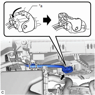
(e) Connect the cooling fan motor connector and push down the lock lever to engage the claw as shown in the illustration.
NOTICE:
- When connecting the cooling fan motor connector, make sure that the connecting parts of the cooling fan motor connector are free of dirt, water or other foreign matter.
- Be sure to securely connect the cooling fan motor connector.
(f) Engage the 2 guides.
(g) Engage the 2 claws to install the cooler condenser assembly to the radiator assembly.
NOTICE:
Make sure not to damage the cooler condenser assembly when installing the cooler condenser assembly.
4. CONNECT NO. 2 RADIATOR HOSE
(a) Connect the No. 2 radiator hose to the radiator assembly and slide the clip to secure it.
5. CONNECT NO. 1 RADIATOR HOSE
(a) Connect the No. 1 radiator hose to the radiator assembly and slide the clip to secure it.
(b) Engage the clamp to connect the No. 1 radiator hose to the fan with motor assembly.
6. CONNECT NO. 6 WATER BY-PASS HOSE
(a) Connect the No. 6 water by-pass hose to the radiator assembly.
7. CONNECT NO. 5 WATER BY-PASS HOSE
(a) Connect the No. 5 water by-pass hose to the radiator assembly and slide the clip to secure it.
8. INSTALL UPPER RADIATOR SUPPORT SUB-ASSEMBLY
(a) Install the upper radiator support sub-assembly with the 4 bolts.
Torque:
12.5 N·m {127 kgf·cm, 9 ft·lbf}
(b) Engage the 4 clamps to connect the wire harness to the upper radiator support sub-assembly.
(c) Engage the clamp to connect the hood lock control cable assembly to the upper radiator support sub-assembly.
9. INSTALL NO. 1 RADIATOR AIR GUIDE RH
(a) Engage the guide and claw.
(b) Install the No. 1 radiator air guide RH with the clip.
10. INSTALL NO. 1 RADIATOR AIR GUIDE LH
(a) Engage the guide and claw.
(b) Install the No. 1 radiator air guide LH with the front radiator side air guide plate LH with the clip.
11. INSTALL UPPER RADIATOR MOUNTING BRACKET
(a) Install the 2 upper radiator mounting brackets with the 2 bolts and 2 nuts.
Torque:
12.5 N·m {127 kgf·cm, 9 ft·lbf}
(b) Connect the 2 horn connectors.
12. INSTALL INLET AIR CLEANER ASSEMBLY
Click here .gif)
13. INSTALL HOOD LOCK ASSEMBLY
Click here
14. INSTALL FRONT BUMPER REINFORCEMENT SUB-ASSEMBLY
Click here
15. INSTALL NO. 2 FRONT BUMPER MOUNTING BRACKET
Click here
16. INSTALL FRONT BUMPER ENERGY ABSORBER
Click here
17. INSTALL THERMISTOR ASSEMBLY
Click here
18. INSTALL HEADLIGHT ASSEMBLY
for LED Type Turn Signal Light: Click here
for Bulb Type Turn Signal Light: Click here
19. ADD ENGINE COOLANT
Click here
20. INSPECT FOR COOLANT LEAK
Click here
21. INSTALL NO. 2 ENGINE UNDER COVER ASSEMBLY
Click here
22. INSTALL NO. 1 ENGINE UNDER COVER
Click here
23. INSTALL FRONT WHEEL OPENING EXTENSION PAD RH
Click here
24. INSTALL FRONT WHEEL OPENING EXTENSION PAD LH
Click here
READ NEXT:
 Thermostat
ComponentsCOMPONENTS ILLUSTRATION *1 NO. 2 RADIATOR HOSE *2 WATER INLET WITH THERMOSTAT SUB-ASSEMBLY *3 GASKET *4 NO. 7 WATER BY-PASS HOSE N*m (kgf*cm, ft.*lbf): Specified
Water Pump
ComponentsCOMPONENTS ILLUSTRATION *1 ENGINE WATER PUMP ASSEMBLY (WATER INLET HOUSING) *2 GASKET *3 STUD BOLT - - N*m (kgf*cm, ft.*lbf): Specified torque ● Non-reusabl
SEE MORE:
Main Body ECU Vehicle Information Reading/Writing Process Malfunction (B15F6)
DESCRIPTION This DTC is stored when items controlled by the main body ECU (multiplex network body ECU) cannot be customized via the navigation system vehicle customization screen. HINT: The main body ECU (multiplex network body ECU) controls the items for the following systems that are customizable
Reassembly
REASSEMBLY CAUTION / NOTICE / HINT HINT:
Use the same procedure for the RH side and LH side.
The following procedure is for the LH side.
PROCEDURE 1. PRECAUTION NOTICE: After turning the engine switch (for Gasoline Model) or power switch (for HV Model) off, waiting time may be required befor
