Lexus ES: Installation
INSTALLATION
PROCEDURE
1. INSTALL FLOW SHUTTING VALVE (NO. 1 WATER BY-PASS HOSE)
(a) Install the flow shutting valve (No. 1 water by-pass hose) with the bolt.
Torque:
19 N·m {194 kgf·cm, 14 ft·lbf}
(b) Connect the flow shutting valve (No. 1 water by-pass hose) connector.
(c) Connect the flow shutting valve (No. 1 water by-pass hose) to the transmission oil cooler and slide the clip to secure it.
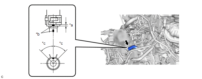
| *a | 2 to 7 mm (0.0787 to 0.276 in.) | *b | Paint Mark |
| *c | 45° (Tabs of Clip Installation Area) | - | - |
NOTICE:
- Make sure to slide the flow shutting valve (No. 1 water by-pass hose) until it contacts the hose stopper of the transmission oil cooler.
- Make sure to align the paint mark of the flow shutting valve (No. 1 water by-pass hose) with the paint mark of the transmission oil cooler.
- Make sure that the tabs of the clip are within the area shown in the illustration.
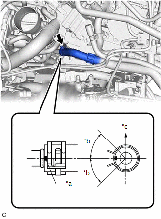
| (d) Connect the flow shutting valve (No. 1 water by-pass hose) to the water outlet and slide the clip to secure it. NOTICE:
|
|
(e) Engage the 2 clamps to connect the flow shutting valve (No. 1 water by-pass hose) and transmission breather hose to the hose clamp.
(f) Engage the 3 clamps to install the hose clamp.
(g) Engage the 3 clamps to install the transmission breather clamp.
2. INSTALL BATTERY CLAMP SUB-ASSEMBLY
Click here .gif)
3. INSTALL BATTERY
Click here
4. INSTALL ECM
Click here
5. ADD ENGINE COOLANT
Click here
6. INSPECT FOR COOLANT LEAK
Click here
7. INSTALL FRONT FENDER APRON SEAL LH
Click here
8. INSTALL NO. 2 ENGINE UNDER COVER ASSEMBLY
Click here
9. INSTALL NO. 1 ENGINE UNDER COVER
Click here
10. INSTALL FRONT WHEEL OPENING EXTENSION PAD RH
Click here
11. INSTALL FRONT WHEEL OPENING EXTENSION PAD LH
Click here
12. INSTALL FRONT WHEEL LH
Click here
READ NEXT:
 Components
COMPONENTS ILLUSTRATION *1 FLOW SHUTTING VALVE (WATER BY-PASS HOSE ASSEMBLY) *2 VACUUM HOSE *3 ENGINE WIRE HARNESS *4 OUTLET HEATER HOSE *5 INLET HEATER HOSE *6 NO. 2 WAT
Inspection
INSPECTION PROCEDURE 1. INSPECT FLOW SHUTTING VALVE (WATER BY-PASS HOSE ASSEMBLY) (a) Measure the resistance according to the value(s) in the table below. Standard Resistance: Tester Connection
SEE MORE:
Position Initialization Incomplete (Fr Shade) (B2348)
DESCRIPTION This DTC is stored when the roof sunshade ECU (sliding roof drive gear assembly) has not been initialized. DTC No. Detection Item DTC Detection Condition Trouble Area B2348 Position Initialization Incomplete (Fr Shade) Roof sunshade ECU (sliding roof drive gear assembly)
Dcm Operation History
DCM OPERATION HISTORY DCM OPERATION HISTORY HINT:
This function shows the telematics network status when the DCM (telematics transceiver) was operated. Use this when no DTC is present but this telematics system was unable to connect to the call center. This symptom may occur if cell phone signal
