Lexus ES: Installation
INSTALLATION
PROCEDURE
1. INSTALL LEAK DETECTION PUMP SUB-ASSEMBLY
HINT:
Only perform this procedure when replacement of the leak detection pump sub-assembly is necessary.
| (a) Engage the 2 claws to install a new leak detection pump sub-assembly to the No. 2 charcoal canister sub-assembly. NOTICE:
|
|
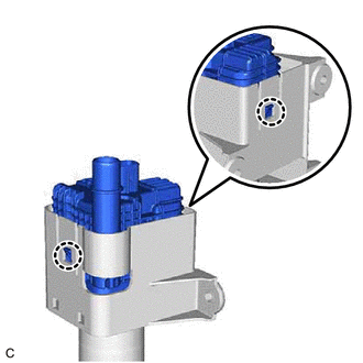
2. INSTALL NO. 2 CHARCOAL CANISTER SUB-ASSEMBLY
(a) Install the No. 2 charcoal canister sub-assembly to the vehicle body with the 3 nuts.
Torque:
8.0 N·m {82 kgf·cm, 71 in·lbf}
(b) Connect the leak detection pump sub-assembly connector.
(c) Push in the air line tube to the pipe (leak detection pump sub-assembly) until the air line tube makes a "click" sound.
NOTICE:
- Check that there are no scratches or foreign matter around the connecting parts of the tube connector and pipe (leak detection pump sub-assembly) before performing this work.
- After connecting the air line tube, check that the air line tube is securely connected by pulling on the tube connector.
3. INSTALL CANISTER (CHARCOAL CANISTER ASSEMBLY)
(a) Install the clip to the vehicle body.
| (b) Engage the claw to install the canister (charcoal canister assembly) to the vehicle body as shown in the illustration. |
|
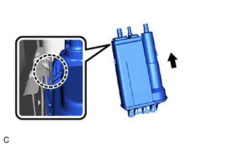
(c) Engage the clip to the canister (charcoal canister assembly).
(d) Install the 2 bolts.
Torque:
8.0 N·m {82 kgf·cm, 71 in·lbf}
(e) Connect the purge line hose to the canister (charcoal canister assembly) and slide the clip to secure it.
(f) Push the vent line hose onto the canister (charcoal canister assembly) and push in the retainer to engage the lock claws.
NOTICE:
- Check that there are no scratches or foreign matter around the connecting parts of the tube connector and pipe (canister (charcoal canister assembly)) before performing this work.
- After connecting the vent line hose, check that the vent line hose is securely connected by pulling on the tube connector.
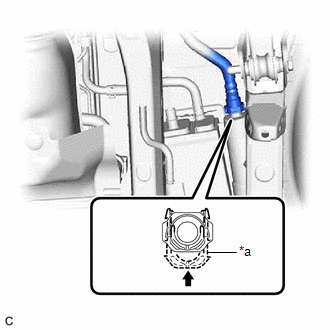
| *a | Retainer |
.png) | Push in |
(g) Push the fuel tank vent hose onto the canister (charcoal canister assembly) and push in the retainer to engage the lock claws.
NOTICE:
- Check that there are no scratches or foreign matter around the connecting parts of the tube connector and pipe (canister (charcoal canister assembly)) before performing this work.
- After connecting the fuel tank vent hose, check that the fuel tank vent hose is securely connected by pulling on the tube connector.
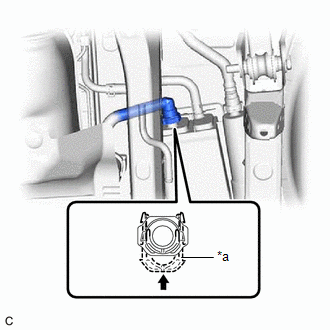
| *a | Retainer |
| | Push in |
4. INSTALL REAR NO. 1 STABILIZER BAR BRACKET
(a) Install the 2 rear No. 1 stabilizer bar brackets to the vehicle body with the 4 bolts.
Torque:
78 N·m {795 kgf·cm, 58 ft·lbf}
5. INSTALL CENTER EXHAUST PIPE ASSEMBLY
(a) Install 3 new gaskets to the front exhaust pipe assembly (TWC: Rear Catalyst) and center exhaust pipe assembly.
(b) Connect the center exhaust pipe assembly to the 2 exhaust pipe supports.
(c) Install the center exhaust pipe assembly to the front exhaust pipe assembly (TWC: Rear Catalyst), tail exhaust pipe assembly and tail exhaust pipe assembly LH with 6 new bolts and 2 new nuts.
Torque:
43 N·m {438 kgf·cm, 32 ft·lbf}
6. INSTALL CENTER FLOOR CROSSMEMBER BRACE
Click here .gif)
7. INSTALL FRONT CENTER FLOOR BRACE
Click here
8. INSTALL FRONT FLOOR COVER LH
Click here
9. INSTALL FRONT FLOOR COVER RH
Click here
10. INSPECT FOR EXHAUST GAS LEAK
Click here
READ NEXT:
 Parts Location
PARTS LOCATION ILLUSTRATION *1 CANISTER (CHARCOAL CANISTER ASSEMBLY) *2 FUEL TANK CAP ASSEMBLY *3 PCV VALVE (VENTILATION VALVE SUB-ASSEMBLY) *4 PURGE VALVE (PURGE VSV) *5 ECM
System Diagram
SYSTEM DIAGRAM *1 Purge Valve (Purge VSV) *2 Fuel Tank Cap Assembly *3 Fuel Tank Assembly *4 Canister Filter *5 Fuel Cut-off Valve *6 ECM *7 Canister Pump Module (L
SEE MORE:
Installation
INSTALLATION PROCEDURE 1. INSTALL ENGINE WATER PUMP ASSEMBLY (a) Install a new water pump gasket and the engine water pump assembly with the 15 bolts. Torque: Bolt (A) : 43 N·m {438 kgf·cm, 32 ft·lbf} Bolt (B) : 21 N·m {214 kgf·cm, 15 ft·lbf} Bolt (C) : 11 N·m {112 kgf·cm, 8 ft·lbf}
ABS Operates Before Necessary When Braking
DESCRIPTION Troubleshooting for when ABS operates too soon due to a noisy signal from the speed sensor, a difference in output, etc. PROCEDURE 1. PERFORM TEST MODE (SIGNAL CHECK) INSPECTION (SPEED SENSOR CIRCUIT) (a) Using the Techstream, perform a Test Mode (Signal Check) inspection sensor
