Lexus ES: Dtc Check / Clear
DTC CHECK / CLEAR
CHECK DTCs (USING TECHSTREAM)
(a) Turn the engine switch off.
(b) Connect the Techstream to the DLC3.
(c) Turn the engine switch on (IG).
(d) Turn the Techstream on.
(e) Enter the following menus: Chassis / EMPS / Trouble Codes.
Chassis > EMPS > Trouble Codes(f) Check the details of the DTCs.
Click here .gif)
CHECK DTCs (USING SST CHECK WIRE)
(a) Using SST, connect terminals G57-13 (TC) and G57-4 (CG) of the DLC3.
SST: 09843-18040
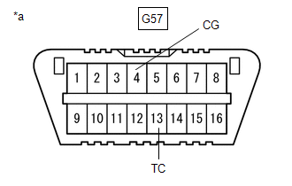
| *a | DLC3 |
(b) Turn the engine switch on (IG).
(c) Read and write down any DTCs indicated by the blinking of the EPS warning light in the combination meter assembly. Refer to the illustration to the right for examples of the normal system code and DTCs 21 and 22.
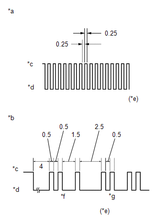
| *a | Normal System Code |
| *b | Codes 21 and 22 |
| *c | ON |
| *d | OFF |
| *e | Seconds |
| *f | Code 21 |
| *g | Code 22 |
HINT:
-
If the EPS warning light does not blink to display stored DTCs or the normal system code, inspect the circuit shown in the table below.
Trouble Area
Link
EPS warning light circuit
- If two or more malfunctions are detected simultaneously, DTCs will be displayed in ascending numerical order.
(d) Refer to Diagnostic Trouble Code Chart for DTC information.
Click here
(e) Check the details of the DTCs.
EPS DTC| EPS Warning Light Display | Tester Display |
|---|---|
| 11 | C1511 |
| C1512 | |
| C1513 | |
| C1514 | |
| 12 | C1528 |
| 13 | C1541 |
| 15 | C1515 |
| 16 | C1516 |
| 22 | C1552 |
| 23 | C1554 |
| 24 | C1521 |
| C1522 | |
| C1523 | |
| 25 | C1531 |
| C1532 | |
| C1533 | |
| C1534 | |
| C1551 | |
| C1555 | |
| 26 | C1581 |
| C1582 | |
| 41 | U0100 |
| 42 | U0129 |
| 43 | U0132 |
| 44 | C1567 |
| 45 | U023A |
| 47 | U0126 |
CLEAR DTCs (USING TECHSTREAM)
(a) Turn the engine switch off.
(b) Connect the Techstream to the DLC3.
(c) Turn the engine switch on (IG).
(d) Turn the Techstream on.
(e) Enter the following menus: Chassis / EMPS / Trouble Codes.
Chassis > EMPS > Trouble Codes(f) Clear the DTCs.
Chassis > EMPS > Clear DTCs(g) Turn the engine switch off.
(h) Disconnect the Techstream from the DLC3.
READ NEXT:
 Dtc Check / Clear
DTC CHECK / CLEAR CHECK DTCs (USING TECHSTREAM) (a) Turn the engine switch off. (b) Connect the Techstream to the DLC3. (c) Turn the engine switch on (IG). (d) Turn the Techstream on. (e) Enter the fo
Freeze Frame Data
FREEZE FRAME DATA FREEZE FRAME DATA NOTICE:
It is difficult to show the specified values (judgment values) clearly because freeze frame data values change significantly due to differences in measur
Fail-safe Chart
FAIL-SAFE CHART If a problem occurs in the power steering system, the power steering assist will be stopped or the amount of power assist will be decreased to protect the system. Power Steering System
SEE MORE:
Reassembly
REASSEMBLY PROCEDURE 1. INSTALL SUNSHADE TRIM SUB-ASSEMBLY (a) Make sure that the No. 1 sliding roof shoe sub-assembly is positioned as shown in the illustration. HINT: Use the same procedure for the RH side and LH side. *a No. 1 Sliding Roof Shoe Sub-assembly *b Cutout
Problem Symptoms Table
PROBLEM SYMPTOMS TABLE HINT:
Use the table below to help determine the cause of problem symptoms. If multiple suspected areas are listed, the potential causes of the symptoms are listed in order of probability in the "Suspected Area" column of the table.
Check each symptom by checking the suspe
