Lexus ES: Installation
INSTALLATION
PROCEDURE
1. INSTALL NO. 1 MOTOR COOLING HOSE
HINT:
Perform this procedure only when replacement of the motor cooling cooler is necessary.
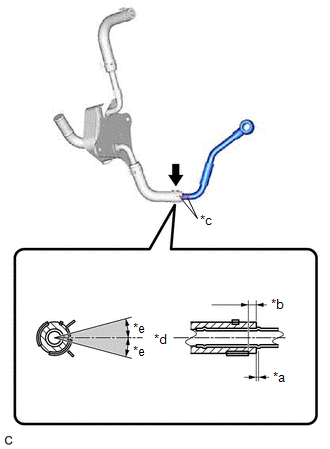
(a) Coat the pipe of the motor cooling cooler with a small amount of ATF as shown in the illustration.
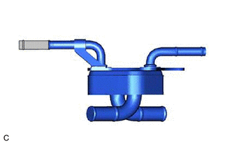
.png) | ATF Application Area |
(b) Install the No. 1 motor cooling hose to the motor cooling cooler, and slide the clip to secure it.
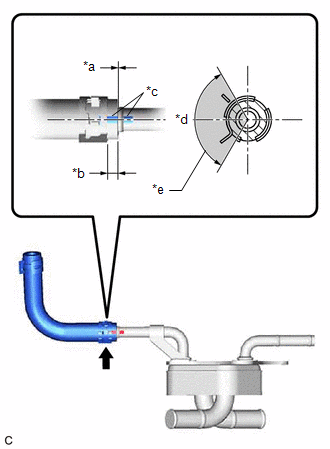
| *a | 0 to 3 mm (0 to 0.118 in.) |
| *b | 2 to 7 mm (0.0787 to 0.276 in.) |
| *c | Paint Mark |
| *d | Center of Paint Mark |
| *e | 120° |
| | Claw of Clip Location |
NOTICE:
- Be careful not to deform the motor cooling cooler.
- Make sure to align the paint mark of the No. 1 motor cooling hose with the paint mark of the motor cooling cooler.
- Make sure that the claws of the clip are positioned within the area shown in the illustration.
2. INSTALL NO. 2 MOTOR COOLING HOSE
HINT:
Perform this procedure only when replacement of the motor cooling cooler is necessary.
(a) Coat the pipe of the motor cooling cooler with a small amount of ATF as shown in the illustration.
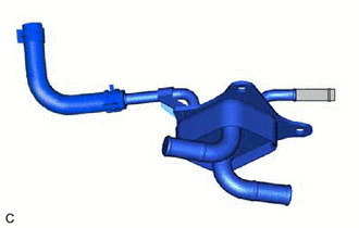
| | ATF Application Area |
(b) Install the No. 2 motor cooling hose to the motor cooling cooler, and slide the clip to secure it.
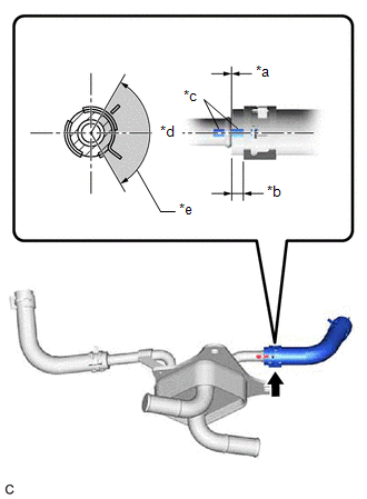
| *a | 0 to 3 mm (0 to 0.118 in.) |
| *b | 2 to 7 mm (0.0787 to 0.276 in.) |
| *c | Paint Mark |
| *d | Center of Paint Mark |
| *e | 120° |
| | Claw of Clip Location |
NOTICE:
- Be careful not to deform the motor cooling cooler.
- Make sure to align the paint mark of the No. 2 motor cooling hose with the paint mark of the motor cooling cooler.
- Make sure that the claws of the clip are positioned within the area shown in the illustration.
3. INSTALL NO. 2 MOTOR COOLING PIPE
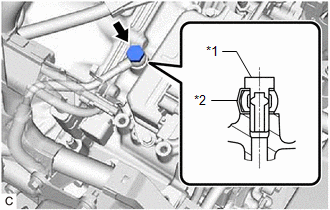
(a) Install the No. 2 motor cooling pipe to the No. 2 motor cooling hose, and slide the clip to secure it.
| *a | 0 to 3 mm (0 to 0.118 in.) |
| *b | 2 to 7 mm (0.0787 to 0.276 in.) |
| *c | Paint Mark |
| *d | Center of Paint Mark |
| *e | 15° |
| | Center of Clip Location |
NOTICE:
- Make sure to align the paint mark of the No. 2 motor cooling pipe with the paint mark of the No. 2 motor cooling hose.
- Make sure that the center of the clip (between the claws of the clip) is within 15° of the center of the paint mark as shown in the illustration.
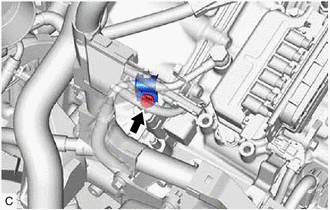
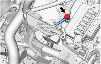
4. INSTALL MOTOR COOLING COOLER
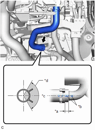
(a) Connect the No. 1 motor cooling hose to the transaxle housing tube connector, and slide the clip to secure it.
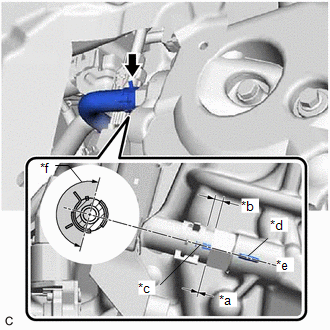
| *a | 0 to 3 mm (0 to 0.118 in.) |
| *b | 2 to 7 mm (0.0787 to 0.276 in.) |
| *c | Paint Mark |
| *d | Rib |
| *e | Center of Rib |
| *f | 180° |
| | Claw of Clip Location |
NOTICE:
- Make sure to align the paint mark of the No. 1 motor cooling hose with the rib of the hybrid vehicle transaxle assembly.
- Make sure that the claws of the clip are within the location shown in the illustration.
| (b) Temporarily install the motor cooling cooler to the No. 1 transmission control cable bracket with the 3 bolts. |
|
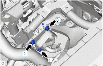
(c) Tighten the 3 bolts in the order shown in the illustration.
Torque:
11.5 N·m {117 kgf·cm, 8 ft·lbf}
| (d) Temporarily install the No. 2 motor cooling pipe to the hybrid vehicle transaxle assembly with the oil cooler union bolt and a new gasket. |
|
| (e) Install the No. 2 motor cooling pipe to the hose bracket with the bolt and No. 1 oil cooler tube clamp. Torque: 11.5 N·m {117 kgf·cm, 8 ft·lbf} |
|
| (f) Tighten the oil cooler union bolt. Torque: 35 N·m {357 kgf·cm, 26 ft·lbf} |
|
5. CONNECT NO. 5 INVERTER COOLING HOSE
Click here .gif)
6. INSTALL NO. 1 INVERTER COOLING HOSE
(a) Install the No. 1 inverter cooling hose to the motor cooling cooler, and slide the clip to secure it.
| *a | 2 to 7 mm (0.0787 to 0.276 in.) |
| *b | Paint Mark |
| *c | Center of Paint Mark |
| *d | 120° |
| | Claw of Clip Location |
NOTICE:
- Be careful not to deform the motor cooling cooler.
- Make sure to align the paint mark of the No. 1 inverter cooling hose with the paint mark of the motor cooling cooler.
- Make sure that the claws of the clip are positioned within the area shown in the illustration.
7. INSTALL INVERTER WITH CONVERTER ASSEMBLY
Click here
8. INSPECT HYBRID TRANSAXLE FLUID
Click here
9. INSPECT FOR HYBRID TRANSAXLE FLUID LEAK
10. INSTALL FRONT FENDER APRON SEAL LH
Click here
11. INSTALL NO. 2 ENGINE UNDER COVER ASSEMBLY
Click here
12. INSTALL NO. 1 ENGINE UNDER COVER
Click here
13. INSTALL FRONT WHEEL OPENING EXTENSION PAD LH
Click here
14. INSTALL FRONT WHEEL OPENING EXTENSION PAD RH
Click here
READ NEXT:
 Removal
REMOVAL CAUTION / NOTICE / HINT The necessary procedures (adjustment, calibration, initialization, or registration) that must be performed after parts are removed and installed, or replaced during mot
Shift Lever Knob
ComponentsCOMPONENTS ILLUSTRATION *1 SHIFT LEVER KNOB SUB-ASSEMBLY - - InstallationINSTALLATION PROCEDURE 1. INSTALL SHIFT LEVER KNOB SUB-ASSEMBLY (a) Install the shift lever knob su
SEE MORE:
Fuel Level Sensor "A" Circuit Short to Battery (P046012,P046014)
DESCRIPTION The fuel sender gauge is located inside the fuel tank and measures the amount of fuel. The fuel sender gauge converts the fuel level in the fuel tank into a voltage value and outputs it to the combination meter assembly. The ECM determines when it is necessary to refuel the vehicle based
Replacement
REPLACEMENT
CAUTION / NOTICE / HINT
CAUTION:
Do not remove the radiator cap sub-assembly or radiator drain cock plug while
the engine and radiator assembly are still hot. Pressurized, hot engine coolant
and steam may be released and cause serious burns.
PROCEDURE
1. DRAIN ENGINE COOLANT (
