Lexus ES: Removal
REMOVAL
CAUTION / NOTICE / HINT
The necessary procedures (adjustment, calibration, initialization or registration) that must be performed after parts are removed and installed, or replaced during brake master cylinder sub-assembly removal/installation are shown below.
Necessary Procedures After Parts Removed/Installed/Replaced (for Gasoline Model:)| Replaced Part or Performed Procedure | Necessary Procedure | Effect/Inoperative Function when Necessary Procedure not Performed | Link |
|---|---|---|---|
|
*: When performing learning using the Techstream.
Click here | |||
| Battery terminal is disconnected/reconnected | Perform steering sensor zero point calibration | Lane Control System | |
| Pre-collision System | |||
| Parking Support Brake System* | |||
| Lighting System | |||
| Memorize steering angle neutral point | Parking Assist Monitor System | | |
| Panoramic View Monitor System | | ||
| Initialize power trunk lid system | Power Trunk Lid System | | |
NOTICE:
- After the engine switch is turned off, the radio receiver assembly records various types of memory and settings. As a result, after turning the engine switch off, make sure to wait at least 85 seconds before disconnecting the cable from the negative (-) battery terminal. (for Audio and Visual System)
- After the engine switch is turned off, the radio receiver assembly records various types of memory and settings. As a result, after turning the engine switch off, make sure to wait at least 85 seconds before disconnecting the cable from the negative (-) battery terminal. (for Navigation System)
CAUTION / NOTICE / HINT
NOTICE:
Make sure to release vacuum from the brake booster assembly before removing the brake master cylinder sub-assembly from the brake booster assembly.
PROCEDURE
1. PRECAUTION
NOTICE:
After turning the engine switch off, waiting time may be required before disconnecting the cable from the negative (-) battery terminal. Therefore, make sure to read the disconnecting the cable from the negative (-) battery terminal notices before proceeding with work.
2. REMOVE BATTERY
Click here .gif)
3. DRAIN BRAKE FLUID
NOTICE:
If brake fluid leaks onto any painted surface, immediately wash it off.
4. REMOVE BRAKE MASTER CYLINDER SUB-ASSEMBLY
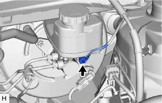
| (a) Disconnect the connector from the brake master cylinder sub-assembly. |
|
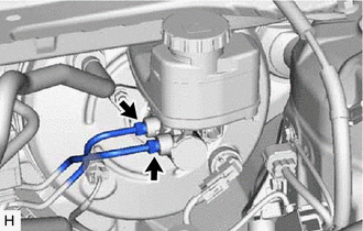
| (b) Using a union nut wrench, disconnect the 2 brake lines from the brake master cylinder sub-assembly. NOTICE:
|
|
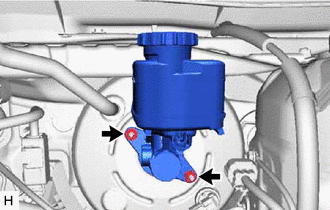
| (c) Remove the 2 nuts and brake master cylinder sub-assembly from the brake booster assembly. NOTICE:
|
|
5. REMOVE BRAKE MASTER CYLINDER O-RING
(a) Remove the brake master cylinder O-ring from the brake master cylinder sub-assembly.
READ NEXT:
 Adjustment
ADJUSTMENT PROCEDURE 1. INSPECT AND ADJUST BRAKE PEDAL HEIGHT (a) Remove the front door scuff plate LH. Click here (b) Remove the cowl side trim board LH. Click here (c) Remove the No. 1 instrumen
Components
COMPONENTS ILLUSTRATION *1 BRAKE LINE *2 BRAKE MASTER CYLINDER SUB-ASSEMBLY Tightening torque for "Major areas involving basic vehicle performance such as moving/turning/stopping" : N
SEE MORE:
Disassembly
DISASSEMBLY PROCEDURE 1. REMOVE ROOF WIND DEFLECTOR PANEL SUB-ASSEMBLY (a) Disengage the 3 claws and 2 pins. (b) Move the roof wind deflector panel sub-assembly in the direction indicated by the arrow (1) shown in the illustration. Remove in this Direction (1) Remove in this Direction
Vehicle Control History
VEHICLE CONTROL HISTORY DESCRIPTION
Vehicle Control History is a function that captures and stores ECU data when triggered by specific vehicle behavior.
If the customer states that the engine stalled or will not start, it may be possible to diagnose the cause of the malfunction by checking the
