Lexus ES: Installation
INSTALLATION
PROCEDURE
1. INSTALL BRAKE BOOSTER GASKET
(a) Install a new brake booster gasket to the brake booster assembly.
2. INSTALL BRAKE BOOSTER ASSEMBLY
(a) Temporarily install the brake booster assembly to the vehicle body.
NOTICE:
Do not apply excessive force to the brake lines.
(b) Temporarily install the lock nut and brake master cylinder push rod clevis to the brake booster assembly.
NOTICE:
Fully tighten the lock nut when adjusting the brake pedal height.
(c) Install the 4 nuts to secure the brake booster assembly.
Torque:
12.8 N·m {131 kgf·cm, 9 ft·lbf}
(d) Connect the connector to the vacuum warning switch assembly.
3. INSTALL BRAKE PEDAL LINK PIN
Click here .gif)
4. CONNECT UNION TO CHECK VALVE HOSE
(a) Connect the union to check valve hose to the brake booster assembly, and slide the clip to secure it.
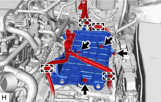
5. INSTALL BATTERY CLAMP SUB-ASSEMBLY
(a) for A25A-FKS:
| (1) Install the battery clamp sub-assembly with the 3 bolts and nut. Torque: Bolt : 18.5 N·m {189 kgf·cm, 14 ft·lbf} Nut : 8.0 N·m {82 kgf·cm, 71 in·lbf} |
|
(2) Engage the 4 clamps to the battery clamp sub-assembly.
(b) for 2GR-FKS:
| (1) Install the battery clamp sub-assembly with the 3 bolts and nut. Torque: Bolt : 18.5 N·m {189 kgf·cm, 14 ft·lbf} Nut : 8.0 N·m {82 kgf·cm, 71 in·lbf} |
|
.png)
(2) Engage the 5 clamps to the battery clamp sub-assembly.
6. INSTALL AIR CLEANER ASSEMBLY WITH AIR CLEANER HOSE (for A25A-FKS)
Click here
7. INSTALL NO. 1 ENGINE COVER SUB-ASSEMBLY (for A25A-FKS)
Click here
8. INSTALL AIR CLEANER ASSEMBLY WITH AIR CLEANER HOSE (for 2GR-FKS)
Click here
9. INSTALL FRONT CENTER UPPER SUSPENSION BRACE SUB-ASSEMBLY
Click here
10. INSTALL COWL TOP VENTILATOR LOUVER SUB-ASSEMBLY
Click here
11. INSTALL NO. 1 INSTRUMENT PANEL UNDER COVER SUB-ASSEMBLY
Click here
12. INSTALL BRAKE MASTER CYLINDER SUB-ASSEMBLY
Click here
13. INSPECT AND ADJUST BRAKE PEDAL
Click here
READ NEXT:
 On-vehicle Inspection
ON-VEHICLE INSPECTION PROCEDURE 1. INSPECT BRAKE BOOSTER ASSEMBLY (a) Airtightness check (1) Start the engine and stop it after 1 or 2 minutes. Slowly depress the brake pedal several times. HINT: I
Reassembly
REASSEMBLY PROCEDURE 1. INSTALL VACUUM WARNING SWITCH ASSEMBLY (a) Install a new check valve grommet to the brake booster assembly. (b) Install the vacuum warning switch assembly to the brake booster
Removal
REMOVAL CAUTION / NOTICE / HINT The necessary procedures (adjustment, calibration, initialization or registration) that must be performed after parts are removed and installed, or replaced during brak
SEE MORE:
Removal
REMOVAL CAUTION / NOTICE / HINT The necessary procedures (adjustment, calibration, initialization, or registration) that must be performed after parts are removed and installed, or replaced during telephone microphone assembly removal/installation are shown below. Necessary Procedure After Parts Rem
Parts Location
PARTS LOCATION ILLUSTRATION *1 SWING GRILLE ACTUATOR ASSEMBLY *2 RADIATOR SHUTTER SUB-ASSEMBLY *3 ECM - - ILLUSTRATION *1 COMBINATION METER ASSEMBLY *2 INSTRUMENT PANEL JUNCTION BLOCK ASSEMBLY - ECU-B NO. 2 FUSE *3 AIR CONDITIONING AMPLIFIER ASSEMBLY *4 HYB
