Lexus ES: Installation
INSTALLATION
PROCEDURE
1. INSTALL BRAKE BOOSTER GASKET
(a) Install a new brake booster gasket to the brake booster assembly.
2. INSTALL BRAKE BOOSTER ASSEMBLY
(a) Temporarily install the brake booster assembly to the vehicle body.
NOTICE:
Do not apply excessive force to the brake lines.
(b) Temporarily install the lock nut and brake master cylinder push rod clevis to the brake booster assembly.
NOTICE:
Fully tighten the lock nut when adjusting the brake pedal height.
(c) Install the 4 nuts to secure the brake booster assembly.
Torque:
12.8 N·m {131 kgf·cm, 9 ft·lbf}
(d) Connect the connector to the vacuum warning switch assembly.
3. INSTALL BRAKE PEDAL LINK PIN
Click here .gif)
4. CONNECT UNION TO CHECK VALVE HOSE
(a) Connect the union to check valve hose to the brake booster assembly, and slide the clip to secure it.
5. INSTALL BATTERY CLAMP SUB-ASSEMBLY
| (a) Install the battery clamp sub-assembly with the 3 bolts and nut. Torque: Bolt : 18.5 N·m {189 kgf·cm, 14 ft·lbf} Nut : 8.0 N·m {82 kgf·cm, 71 in·lbf} |
|
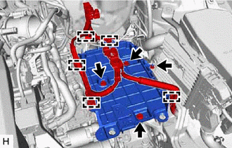
(b) Engage the 5 clamps to the battery clamp sub-assembly.
6. INSTALL AIR CLEANER ASSEMBLY WITH AIR CLEANER HOSE
Click here
7. INSTALL FRONT CENTER UPPER SUSPENSION BRACE SUB-ASSEMBLY
Click here
8. INSTALL COWL TOP VENTILATOR LOUVER SUB-ASSEMBLY
Click here
9. INSTALL NO. 1 INSTRUMENT PANEL UNDER COVER SUB-ASSEMBLY
Click here
10. INSTALL BRAKE MASTER CYLINDER SUB-ASSEMBLY
Click here
11. INSPECT AND ADJUST BRAKE PEDAL
Click here
READ NEXT:
 Installation
INSTALLATION PROCEDURE 1. INSTALL BRAKE BOOSTER GASKET (a) Install a new brake booster gasket to the brake booster assembly. 2. INSTALL BRAKE BOOSTER ASSEMBLY (a) Temporarily install the brake booster
On-vehicle Inspection
ON-VEHICLE INSPECTION PROCEDURE 1. INSPECT BRAKE BOOSTER ASSEMBLY (a) Airtightness check (1) Start the engine and stop it after 1 or 2 minutes. Slowly depress the brake pedal several times. HINT: I
Reassembly
REASSEMBLY PROCEDURE 1. INSTALL VACUUM WARNING SWITCH ASSEMBLY (a) Install a new check valve grommet to the brake booster assembly. (b) Install the vacuum warning switch assembly to the brake booster
SEE MORE:
Installation
INSTALLATION CAUTION / NOTICE / HINT NOTICE: A lock pin is installed to a new steering sensor. Do not remove the lock pin before the steering sensor is installed to the spiral cable sub-assembly. PROCEDURE 1. INSPECT SPIRAL CABLE SUB-ASSEMBLY Click here 2. INSTALL STEERING SENSOR (a) Align the
Absorber Control Actuator(for Front Side)
On-vehicle InspectionON-VEHICLE INSPECTION PROCEDURE 1. INSPECT ABSORBER CONTROL ACTUATOR (a) Measure the resistance according to the value(s) in the table below. Standard Resistance: Tester Connection Condition Specified Condition 1 - 2 15 to 25°C 3.3 to 3.7 Ω If the result
