Lexus ES: Installation
INSTALLATION
CAUTION / NOTICE / HINT
HINT:
- Use the same procedure for the RH side and LH side.
- The following procedure is for the LH side.
- The front speed sensor rotor is a component of the front axle hub sub-assembly. If the front speed sensor rotor is malfunctioning, replace the front axle hub sub-assembly.
PROCEDURE
1. INSTALL FRONT SPEED SENSOR (w/o AVS)
(a) Install the front speed sensor to the steering knuckle with the bolt.
Torque:
8.5 N·m {87 kgf·cm, 75 in·lbf}
NOTICE:
- Keep the tip of the front speed sensor and installation hole free of foreign matter.
- Firmly insert the front speed sensor body into the steering knuckle before tightening the bolt.
- After installing the front speed sensor to the steering knuckle, make sure that there is no clearance between the front speed sensor stay and steering knuckle. Also make sure that no foreign matter is stuck between the parts.
- Do not twist the front speed sensor wire harness when installing it.
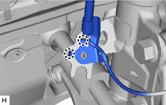
(b) Engage the clamp to install the sensor clamp.
NOTICE:
Do not twist the front speed sensor wire harness when installing it.
| (c) Engage the 2 claws to install the sensor clamp. NOTICE: Do not twist the front speed sensor wire harness when installing it. |
|
| (d) Install the front flexible hose with the bolt. Torque: 29 N·m {296 kgf·cm, 21 ft·lbf} |
|
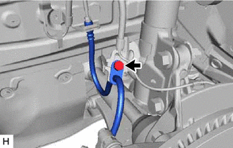
(e) Install the sensor clamp with the bolt.
Torque:
8.5 N·m {87 kgf·cm, 75 in·lbf}
NOTICE:
Do not twist the front speed sensor wire harness when installing it.
(f) Engage the clamp.
NOTICE:
Do not twist the front speed sensor wire harness when installing it.
(g) Connect the front speed sensor connector.
(h) Return the front fender liner to its original position.
2. INSTALL FRONT SPEED SENSOR (w/ AVS)
(a) Install the front speed sensor to the steering knuckle with the bolt.
Torque:
8.5 N·m {87 kgf·cm, 75 in·lbf}
NOTICE:
- Keep the tip of the front speed sensor and installation hole free of foreign matter.
- Firmly insert the front speed sensor body into the steering knuckle before tightening the bolt.
- After installing the front speed sensor to the steering knuckle, make sure that there is no clearance between the front speed sensor stay and steering knuckle. Also make sure that no foreign matter is stuck between the parts.
- Do not twist the front speed sensor wire harness when installing it.
(b) Connect the front speed sensor connector.
3. INSTALL FRONT FENDER LINER (w/o AVS)
(a) Engage the 3 claws to install the front fender liner.
(b) Install the screw and 5 clips.
4. INSTALL FRONT WHEEL OPENING EXTENSION PAD (w/o AVS)
for A25A-FXS: Click here .gif)
for 2GR-FKS: Click here
5. INSTALL FRONT WHEEL
Click here
6. CHECK FOR SPEED SENSOR SIGNAL
for HV Model: Click here
for Gasoline Model: Click here
READ NEXT:
 Installation
INSTALLATION CAUTION / NOTICE / HINT HINT:
Use the same procedure for the RH side and LH side.
The following procedure is for the LH side.
The front speed sensor rotor is a component of the fro
Removal
REMOVAL CAUTION / NOTICE / HINT HINT:
Use the same procedure for the RH side and LH side.
The following procedure is for the LH side.
The front speed sensor rotor is a component of the front ax
Removal
REMOVAL CAUTION / NOTICE / HINT HINT:
Use the same procedure for the RH side and LH side.
The following procedure is for the LH side.
The front speed sensor rotor is a component of the front ax
SEE MORE:
Hybrid/EV Battery Temperature Sensor "A" Signal Stuck In Range (P0A9B2A,...,P306A62)
DESCRIPTION Refer to the description for DTC P0A9B11. Click here DTC No. Detection Item DTC Detection Condition Trouble Area MIL Warning Indicate P0A9B2A Hybrid/EV Battery Temperature Sensor "A" Signal Stuck In Range The performance of battery temperature sensor 0 is abnormal
Inverter Low-voltage Circuit
DESCRIPTION The cause of the malfunction may be the low-voltage circuit. Check whether there is an open circuit in the inverter +B low-voltage power source system or a problem in the communication between the hybrid vehicle control ECU and inverter. Related Parts Check Area Inspection Inver
