Lexus ES: Installation
INSTALLATION
CAUTION / NOTICE / HINT
HINT:
The parking brake indicator light blinks (red) when the engine switch is turned on (IG) after replacing the brake actuator assembly. Operate the electric parking brake switch assembly to turn off the parking brake indicator light.
PROCEDURE
1. INSTALL BRAKE ACTUATOR BRACKET CUSHION
(a) Install the 3 brake actuator bracket cushions to the brake actuator bracket assembly.
2. INSTALL NO. 2 BRAKE ACTUATOR CASE COLLAR
(a) Install the 3 No. 2 brake actuator case collars to the brake actuator bracket cushion.
NOTICE:
Make sure that the No. 2 brake actuator case collar is in full contact with the brake actuator bracket cushion.
(b) Install the 3 nuts.
Torque:
19 N·m {194 kgf·cm, 14 ft·lbf}
3. INSTALL BRAKE ACTUATOR ASSEMBLY
| (a) Install the brake actuator assembly to the brake actuator bracket assembly with the 3 bolts. Torque: 6.5 N·m {66 kgf·cm, 58 in·lbf} NOTICE:
|
|
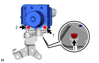
4. INSTALL BRAKE ACTUATOR WITH BRACKET
| (a) Temporarily install the brake actuator with bracket to the vehicle body with the 2 bolts and nut. NOTICE:
HINT:
|
|
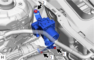
(b) Tighten the 2 bolts and nut in the order shown in the illustration.
Torque:
19 N·m {194 kgf·cm, 14 ft·lbf}
(c) Remove the protective tape.
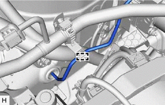
| (d) Engage the clamp to install a new brake tube clamp. |
|
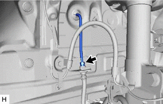
(e) Return the front No. 3 brake tube to its original position.
NOTICE:
Do not apply excessive force to the front No. 3 brake tube.
| (f) Temporarily install the front No. 3 brake tube to the front flexible hose. NOTICE:
|
|
| (g) Engage the clamp to connect the front No. 3 brake tube. NOTICE: Do not kink or damage the front No. 3 brake tube. |
|
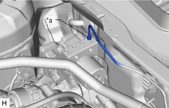
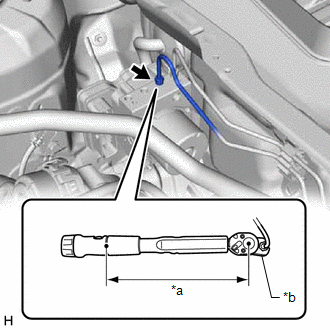
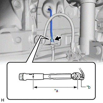
| (h) Temporarily tighten the brake line to the correct position on the brake actuator assembly as shown in the illustration. NOTICE:
|
|
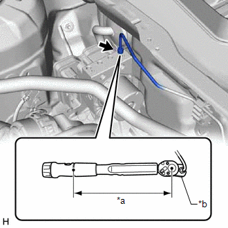
| (i) Using a union nut wrench, fully tighten the brake line. Torque: Specified tightening torque : 15.2 N·m {155 kgf·cm, 11 ft·lbf} NOTICE: Do not kink or damage the brake line. HINT:
|
|
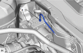
| (j) Temporarily tighten the brake line to the correct position on the brake actuator assembly as shown in the illustration. NOTICE:
|
|
| (k) Using a union nut wrench, fully tighten the brake line. Torque: Specified tightening torque : 15.2 N·m {155 kgf·cm, 11 ft·lbf} NOTICE: Do not kink or damage the brake line. HINT:
|
|
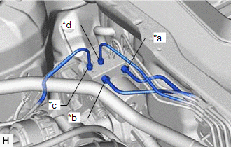
| (l) Temporarily tighten the 4 brake lines to the correct positions on the brake actuator assembly as shown in the illustration. NOTICE:
|
|
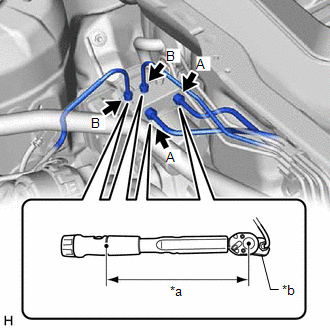
| (m) Using a union nut wrench, fully tighten each brake line. Torque: Specified tightening torque (A) : 19.5 N·m {199 kgf·cm, 14 ft·lbf} Specified tightening torque (B) : 15.2 N·m {155 kgf·cm, 11 ft·lbf} NOTICE: Do not kink or damage the brake lines. HINT:
|
|
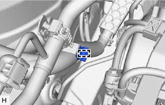
| (n) Engage the 2 clamps to install a new No. 4 brake tube clamp to the brake lines. |
|
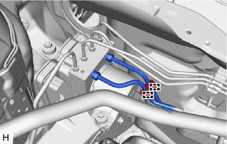
| (o) Using a union nut wrench, fully tighten the front No. 3 brake tube while holding the front flexible hose with a wrench. Torque: Specified tightening torque : 15.2 N·m {155 kgf·cm, 11 ft·lbf} NOTICE: Do not kink or damage the front No. 3 brake tube. HINT:
|
|
(p) Connect the connector to the brake actuator assembly and lock the lock lever.
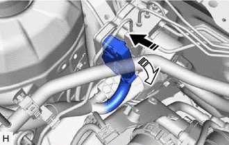
 | Connect the connector |
 | Lock the lock lever |
NOTICE:
- Make sure that the connector is locked securely.
- Make sure that the actuator connector can be connected smoothly.
- Do not allow water, oil or dirt to enter the connector.
5. INSTALL FRONT CENTER UPPER SUSPENSION BRACE SUB-ASSEMBLY
| (a) Temporarily install the front center upper suspension brace sub-assembly with the 6 bolts and 4 nuts. |
|
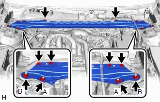
(b) Fully tighten the 2 nuts (A).
Torque:
50 N·m {510 kgf·cm, 37 ft·lbf}
(c) Fully tighten the 6 bolts and 2 nuts (B) to install the front center upper suspension brace sub-assembly.
Bolt:
| Bolt Color | Torque |
|---|---|
| Black | 8.0 N*m (82 kgf*cm, 71 in.*lbf) |
| Silver | 8.9 N*m (91 kgf*cm, 79 in.*lbf) |
Torque:
Nut (B) :
39 N·m {398 kgf·cm, 29 ft·lbf}
(d) Engage the 2 clamps to install the wire harness.
(e) Connect the connector.
(f) w/ Windshield Deicer System:
(1) Engage the 3 clamps to install the wire harness.
(2) Connect the connector.
6. INSTALL COWL TOP VENTILATOR LOUVER SUB-ASSEMBLY
Click here .gif)
7. INSTALL FRONT WHEEL RH
Click here
8. CONNECT CABLE TO NEGATIVE BATTERY TERMINAL
Click here
NOTICE:
When disconnecting the cable, some systems need to be initialized after the cable is reconnected.
Click here
9. BLEED BRAKE SYSTEM
Click here
10. ACCELERATION SENSOR ZERO POINT CALIBRATION AND STORE SYSTEM INFORMATION MEMORIZATION
Click here
11. PERFORM TEST MODE INSPECTION
Click here
12. INSPECT BRAKE ACTUATOR USING GTS
Click here
13. CHECK FOR AND CLEAR DTCS
Click here
READ NEXT:
 On-vehicle Inspection
ON-VEHICLE INSPECTION PROCEDURE 1. CONNECT TECHSTREAM (a) Connect the Techstream to the DLC3 with the ignition switch off. (b) Start the engine and run it at idle. (c) Turn the Techstream on. (d) Ente
Removal
REMOVAL CAUTION / NOTICE / HINT The necessary procedures (adjustment, calibration, initialization or registration) that must be performed after parts are removed and installed, or replaced during brak
SEE MORE:
"B" Camshaft Position Actuator Bank 1 General Electrical Failure (P136201)
DESCRIPTION Refer to DTC P001001. Click here DTC No. Detection Item DTC Detection Condition Trouble Area MIL Memory Note P136201 "B" Camshaft Position Actuator Bank 1 General Electrical Failure While engine is running, malfunction in rotation direction signal (VTD) of cam ti
Camshaft Position Sensor "B" Bank 1 Circuit Short to Ground (P036511,P036515)
DESCRIPTION The camshaft position sensor (for exhaust camshaft) (EV1 signal) consists of a magnet and MRE (Magneto Resistance Element). The exhaust camshaft has a timing rotor for the camshaft position sensor. When the exhaust camshaft rotates, changes occur in the air gaps between the timing rotor
