Lexus ES: Installation
INSTALLATION
PROCEDURE
1. INSTALL PANORAMIC VIEW MONITOR SWITCH (NO. 2 COMBINATION SWITCH ASSEMBLY)
(a) Engage the 4 claws to install the panoramic view monitor switch (No. 2 combination switch assembly) as shown in the illustration.
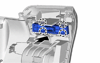
.png) | Install in this Direction |
2. INSTALL LOWER INSTRUMENT PANEL FINISH PANEL SUB-ASSEMBLY
Click here .gif)
3. INSTALL NO. 1 INSTRUMENT PANEL UNDER COVER SUB-ASSEMBLY
Click here
4. INSTALL INSTRUMENT SIDE PANEL LH
Click here
5. INSTALL FRONT DOOR OPENING TRIM COVER LH
Click here
6. INSTALL COWL SIDE TRIM BOARD LH
Click here
7. INSTALL FRONT DOOR SCUFF PLATE LH
Click here
READ NEXT:
 Removal
REMOVAL PROCEDURE 1. REMOVE FRONT DOOR SCUFF PLATE LH Click here 2. REMOVE COWL SIDE TRIM BOARD LH Click here 3. REMOVE FRONT DOOR OPENING TRIM COVER LH Click here 4. REMOVE INSTRUMENT SIDE PANE
"CHK" message(s) are displayed on the SIGNAL CHECK screen.
DESCRIPTION On the SIGNAL CHECK screen, it is possible to check if the signals sent to the parking assist ECU are normal. Click here HINT:
On the SIGNAL CHECK screen, "OK" (blue) is displayed for
SEE MORE:
Camera ECU Malfunction (C1610)
DESCRIPTION This DTC is stored when a malfunction occurs in the parking assist monitor system*1 or panoramic view monitor system*2. DTC No. Detection Item DTC Detection Condition Trouble Area C1610 Camera ECU Malfunction Malfunction occurs in the parking assist monitor system*1 Malf
Front Passenger Side Power Window does not Operate with Front Passenger Side Power Window Switch
DESCRIPTION When the power switch is on (IG), the power window regulator motor assembly (for front passenger door) is operated by the power window regulator switch assembly. The power window regulator motor assembly (for front passenger door) has motor, regulator, and ECU functions. WIRING DIAGRAM
© 2016-2026 Copyright www.lexguide.net
