Lexus ES: Inspection
INSPECTION
PROCEDURE
1. INSPECT STEERING WHEEL SWITCH HOUSING
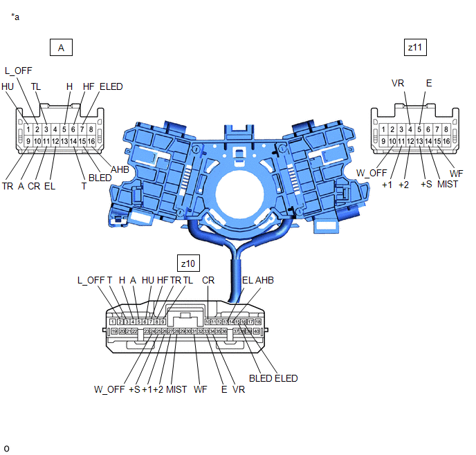
| *a | Component without harness connected (Steering Wheel Switch Housing) | - | - |
(a) Measure the resistance according to the value(s) in the table below.
Standard Resistance:
Light Switch Circuit| Tester Connection | Condition | Specified Condition |
|---|---|---|
| A-2 (L_OFF) - z10-2 (L_OFF) | Always | Below 1 Ω |
| A-14 (T) - z10-3 (T) | Always | Below 1 Ω |
| A-5 (H) - z10-4 (H) | Always | Below 1 Ω |
| A-10 (A) - z10-5 (A) | Always | Below 1 Ω |
| A-1 (HU) - z10-6 (HU) | Always | Below 1 Ω |
| A-6 (HF) - z10-7 (HF) | Always | Below 1 Ω |
| A-9 (TR) - z10-8 (TR) | Always | Below 1 Ω |
| A-3 (TL) - z10-9 (TL) | Always | Below 1 Ω |
| A-11 (CR) - z10-10 (CR) | Always | Below 1 Ω |
| A-12 (EL) - z10-13 (EL) | Always | Below 1 Ω |
| A-16 (AHB) - z10-14 (AHB) | Always | Below 1 Ω |
| A-15 (BLED) - z10-15 (BLED) | Always | Below 1 Ω |
| A-7 (ELED) - z10-16 (ELED) | Always | Below 1 Ω |
| Tester Connection | Condition | Specified Condition |
|---|---|---|
| z11-10 (W_OFF) - z10-24 (W_OFF) | Always | Below 1 Ω |
| z11-13 (+S) - z10-25 (+S) | Always | Below 1 Ω |
| z11-11 (+1) - z10-26 (+1) | Always | Below 1 Ω |
| z11-12 (+2) - z10-27 (+2) | Always | Below 1 Ω |
| z11-14 (MIST) - z10-28 (MIST) | Always | Below 1 Ω |
| z11-15 (WF) - z10-31 (WF) | Always | Below 1 Ω |
| z11-5 (E) - z10-33 (E) | Always | Below 1 Ω |
| z11-4 (VR) - z10-34 (VR) | Always | Below 1 Ω |
If the result is not as specified, replace the steering wheel switch housing.
READ NEXT:
 Installation
INSTALLATION PROCEDURE 1. INSTALL STEERING WHEEL SWITCH HOUSING (a) When reusing the steering wheel switch housing: (1) Using pliers, expand the clamp and temporarily install the steering wheel swi
SEE MORE:
Customize Parameters
CUSTOMIZE PARAMETERS CUSTOMIZE TELEMATICS SYSTEM (a) Customizing with the Techstream. NOTICE:
When the customer requests a change in a function, first make sure that the function can be customized.
Be sure to make a note of the current settings before customizing.
When troubleshooting a funct
Dtc Check / Clear
DTC CHECK / CLEAR CHECK DTC (a) Connect the Techstream to the DLC3. (b) Turn the power switch on (IG). (c) Turn the Techstream on. (d) Enter the following menus: Chassis / Lane Control / Trouble Codes. Chassis > Lane Control > Trouble Codes (e) Check for DTCs (Test Failed / Pending / Confirmed
