Lexus ES: Inspection
INSPECTION
PROCEDURE
1. INSPECT FRONT DOOR ILLUMINATION LIGHT LH (FRONT DOOR OUTSIDE HANDLE ASSEMBLY LH)
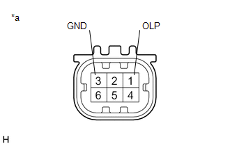
| *a | Component without harness connected (Front Door Illumination Light LH (Front Door Outside Handle Assembly LH)) |
(a) Connect 4 dry-cell batteries (1.5 V) in series.
NOTICE:
Do not use rechargeable batteries as they may not output a voltage of 1.5 V.
(b) Apply 6.0 V battery voltage to the front door illumination light LH (front door outside handle assembly LH) and check that the light illuminates.
OK:
| Measurement Condition | Specified Condition |
|---|---|
| Positive (+) lead from the batteries → Terminal 1 (OLP) Negative (-) lead from the batteries → Terminal 3 (GND) | Illumination light illuminates |
If the result is not as specified, replace the front door illumination light LH (front door outside handle assembly LH).
2. INSPECT FRONT DOOR ILLUMINATION LIGHT RH (FRONT DOOR OUTSIDE HANDLE ASSEMBLY RH)
| *a | Component without harness connected (Front Door Illumination Light RH (Front Door Outside Handle Assembly RH)) |
(a) Connect 4 dry-cell batteries (1.5 V) in series.
NOTICE:
Do not use rechargeable batteries as they may not output a voltage of 1.5 V.
(b) Apply 6.0 V battery voltage to the front door illumination light RH (front door outside handle assembly RH) and check that the light illuminates.
OK:
| Measurement Condition | Specified Condition |
|---|---|
| Positive (+) lead from the batteries → Terminal 1 (OLP) Negative (-) lead from the batteries → Terminal 3 (GND) | Illumination light illuminates |
If the result is not as specified, replace the front door illumination light RH (front door outside handle assembly RH).
READ NEXT:
 Installation
INSTALLATION CAUTION / NOTICE / HINT HINT:
Use the same procedure for the RH side and LH side.
The following procedure is for the LH side.
PROCEDURE 1. INSTALL FRONT DOOR ILLUMINATION LIGHT (F
Components
COMPONENTS ILLUSTRATION *1 COURTESY LIGHT ASSEMBLY *2 REAR DOOR ILLUMINATION LIGHT (REAR DOOR OUTSIDE HANDLE ASSEMBLY) *3 REAR DOOR SERVICE HOLE COVER *4 REAR DOOR TRIM BOARD SUB-A
SEE MORE:
Operation Check
OPERATION CHECK LEXUS APP SUITE RESET PROCEDURE (a) Duplicate the problem symptom. (b) Check for DTCs and repair the systems for which any DTCs are output. Click here (c) Check cellular phone compatibility. (1) Check if the cellular phone/vehicle is compatible (Refer to http://www.lexus.com/Mobil
Brake Switch "A" Circuit Open (P057113)
DESCRIPTION When the brakes are applied by the dynamic radar cruise control system, the skid control ECU (brake actuator assembly) operates the stop light switch assembly (stop light control relay) to illuminate the stop lights. If the ECM receives a signal from the skid control ECU (brake actuator
