Lexus ES: Inspection
INSPECTION
PROCEDURE
1. INSPECT POWER WINDOW REGULATOR MOTOR ASSEMBLY (FOR REAR LH DOOR)
| (a) Connect a positive (+) lead from the auxiliary battery to connector terminal 2. NOTICE: Do not connect a positive (+) lead from the auxiliary battery to any terminal other than terminal 2 to avoid damaging the pulse sensor inside the motor. |
|
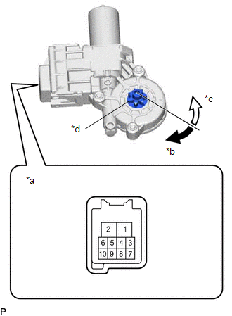
(b) Connect a negative (-) lead from the auxiliary battery to connector terminals 1 and 7 or 10.
(c) Check that the motor gear rotates smoothly as follows:
OK:
| Measurement Condition | Specified Condition |
|---|---|
| Motor gear rotates clockwise |
| Motor gear rotates counterclockwise |
- If the result is not as specified, replace the power window regulator motor assembly (for rear LH door).
CAUTION:
Initialize the power window control system after installing the rear door window regulator assembly.
2. INSPECT POWER WINDOW REGULATOR MOTOR ASSEMBLY (FOR REAR RH DOOR)
| (a) Connect a positive (+) lead from the auxiliary battery to connector terminal 2. NOTICE: Do not connect a positive (+) lead from the auxiliary battery to any terminal other than terminal 2 to avoid damaging the pulse sensor inside the motor. |
|
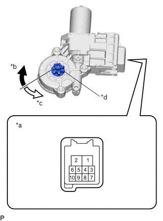
(b) Connect a negative (-) lead from the auxiliary battery to connector terminals 1 and 7 or 10.
(c) Check that the motor gear rotates smoothly as follows:
OK:
| Measurement Condition | Specified Condition |
|---|---|
| Motor gear rotates counterclockwise |
| Motor gear rotates clockwise |
- If the result is not as specified, replace the power window regulator motor assembly (for rear RH door).
CAUTION:
Initialize the power window control system after installing the rear door window regulator assembly.
READ NEXT:
 Installation
INSTALLATION CAUTION / NOTICE / HINT HINT:
Use the same procedure for the RH side and LH side.
The following procedure is for the LH side.
PROCEDURE 1. PRECAUTION NOTICE: After turning the eng
Rear Power Window Switch
ComponentsCOMPONENTS ILLUSTRATION *1 REAR POWER WINDOW REGULATOR SWITCH ASSEMBLY *2 REAR POWER WINDOW REGULATOR SWITCH ASSEMBLY WITH REAR DOOR UPPER ARMREST BASE PANEL RemovalREMOVAL CA
Relay
On-vehicle InspectionON-VEHICLE INSPECTION PROCEDURE 1. INSPECT DEF RELAY (a) Measure the resistance according to the value(s) in the table below. Standard Resistance: Tester Connection Cond
SEE MORE:
A25a-fks Air Cleaner Filter Element
Components
COMPONENTS
ILLUSTRATION
*1
AIR CLEANER CAP SUB-ASSEMBLY
*2
AIR CLEANER FILTER ELEMENT SUB-ASSEMBLY
Removal
REMOVAL
PROCEDURE
1. SEPARATE AIR CLEANER CAP SUB-ASSEMBLY
(a) Disengage the 2 wire harness clamps.
Inspection Mode Procedure
INSPECTION MODE PROCEDURE
INSPECTION MODE (for HV Model)
NOTICE:
When operating the vehicle in an inspection mode for an operation such as a speedometer
test, a DTC may be stored. Therefore, if the warning light illuminates, check for
DTCs using the Techstream and clear the DTCs.
HINT:
If t
