Lexus ES: Inspection
INSPECTION
PROCEDURE
1. INSPECT FUEL PRESSURE SENSOR
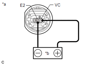
(a) Check the fuel pressure sensor output voltage.
| (1) Apply 5 V between terminals 1 (VC) and 2 (E2). NOTICE:
HINT: If a stable power supply is not available, connect 4 nickel-metal hydride batteries (1.2 V each) or equivalent in series. |
|
| (2) Measure the voltage according to the value(s) in the table below. Standard Voltage:
*: The output voltage changes depending on the voltage applied to the terminals. If the result is not as specified, replace the fuel pressure sensor. |
|
.png)
READ NEXT:
 Installation
INSTALLATION CAUTION / NOTICE / HINT NOTICE: This procedure includes the installation of small-head bolts. Refer to Small-Head Bolts of Basic Repair Hint to identify the small-head bolts. Click here
Components
COMPONENTS ILLUSTRATION *A for Type A *B for Type B *1 FUEL PUMP GAUGE RETAINER *2 FUEL SUCTION TUBE WITH PUMP AND GAUGE ASSEMBLY *3 FUEL TANK MAIN TUBE SUB-ASSEMBLY *4 F
SEE MORE:
Data List / Active Test
DATA LIST / ACTIVE TEST DATA LIST HINT: Using the Techstream to read the Data List allows the values or states of switches, sensors, actuators and other items to be read without removing any parts. This non-intrusive inspection can be very useful because intermittent conditions or signals may be dis
Winter driving tips
Carry out the necessary preparations
and inspections before driving
the vehicle in winter. Always drive
the vehicle in a manner appropriate
to the prevailing weather conditions.
Preparation for winter
Use fluids that are appropriate to
the prevailing outside temperatures.
Engine oil
