
Lexus ES: Inspection
INSPECTION
PROCEDURE
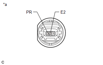
1. INSPECT FUEL PRESSURE SENSOR
(a) Check the fuel pressure sensor output voltage.
| (1) Apply 5 V between terminals 1 (VC) and 2 (E2). NOTICE:
HINT: If a stable power supply is not available, connect 4 nickel-metal hydride batteries (1.2 V each) or equivalent in series. |
|

| (2) Measure the voltage according to the value(s) in the table below. Standard Voltage:
*: The output voltage changes depending on the voltage applied to the terminals. If the result is not as specified, replace the fuel pressure sensor. |
|
READ NEXT:
 Installation
INSTALLATION CAUTION / NOTICE / HINT NOTICE: This procedure includes the installation of small-head bolts. Refer to Small-Head Bolts of Basic Repair Hint to identify the small-head bolts. Click here
Components
COMPONENTS ILLUSTRATION *1 REAR SEAT INNER BELT ASSEMBLY LH *2 REAR CENTER SEAT LAP TYPE BELT ASSEMBLY *3 WASHER *4 REAR SEAT CUSHION ASSEMBLY *5 REAR SEAT CUSHION LOCK HOOK
SEE MORE:
Reassembly
REASSEMBLY CAUTION / NOTICE / HINT NOTICE:
When using a vise, place aluminum plates between the part and vise.
When using a vise, do not overtighten it.
HINT:
Use the same procedure for the RH and LH sides.
The procedure listed below is for the LH side.
PROCEDURE 1. INSTALL OUTBOARD
Fail-safe Chart
FAIL-SAFE CHART PULSE FAILURE (a) If a pulse sensor built into the power window regulator motor assembly malfunctions, the following power window operations will be prohibited. Multiplex Network Master Switch Assembly, Power Window Regulator Switch Assembly, Rear Power Window Regulator Switch Assemb
