Lexus ES: Inspection
INSPECTION
PROCEDURE
1. INSPECT FUEL PRESSURE SENSOR (FUEL DELIVERY PIPE WITH SENSOR ASSEMBLY)
NOTICE:
- Do not remove the fuel pressure sensor from the fuel delivery pipe with sensor assembly.
- If the fuel pressure sensor is removed, replace the fuel pressure sensor (fuel delivery pipe with sensor assembly) with a new one.
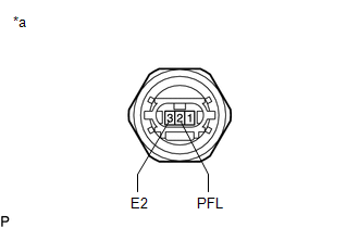
(a) Check the fuel pressure sensor (fuel delivery pipe with sensor assembly) output voltage.
| (1) Apply 5 V between terminals 1 (VC) and 3 (E2). NOTICE:
HINT: If a stable power supply is not available, connect 4 nickel-metal hydride batteries (1.2 V each) or equivalent in series. |
|
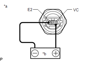
| (2) Measure the voltage according to the value(s) in the table below. Standard Voltage:
*: The output voltage changes depending on the voltage applied to the terminals. If the result is not as specified, replace the fuel pressure sensor (fuel delivery pipe with sensor assembly). |
|
READ NEXT:
 Installation
INSTALLATION PROCEDURE 1. INSTALL FUEL PRESSURE SENSOR (FUEL DELIVERY PIPE WITH SENSOR ASSEMBLY) HINT: Perform "Inspection After Repair" after replacing the fuel pressure sensor (fuel delivery pipe wi
Components
COMPONENTS ILLUSTRATION *A w/ Dust Cap - - *1 FUEL PRESSURE SENSOR (FUEL DELIVERY PIPE WITH SENSOR ASSEMBLY LH) *2 FUEL PIPE PLUG SUB-ASSEMBLY *3 DUST CAP SUB-ASSEMBLY *4
SEE MORE:
Speaker Output Short (B15C3)
DESCRIPTION This DTC is stored when a malfunction occurs in the speakers. DTC No. Detection Item DTC Detection Condition Trouble Area B15C3 Speaker Output Short A short is detected in the speaker output circuit.
Harness or connector
Speaker
Stereo component amplifier assemb
Slip Indicator Light does not Come ON
DESCRIPTION The skid control ECU (brake actuator assembly) controls the slip indicator light in the combination meter assembly via CAN communication. CAUTION / NOTICE / HINT NOTICE: After replacing the skid control ECU (brake actuator assembly), perform acceleration sensor zero point calibration and
